Blogs
How UAVs Send Video Over Radio Links: Codecs, Latency, and Transport Protocols
Published
A technical guide to UAV video links covering H.264, H.265, RTSP, RTP, UDP, TCP, SRT, WebRTC, latency budgets, bitrate planning, and radio-link behavior.
Article
Overview.
A UAV video link is more than a camera and a radio. This technical guide explains how codecs, bitrate, latency, RTSP, UDP, TCP, SRT, and WebRTC affect drone video performance over wireless data links.
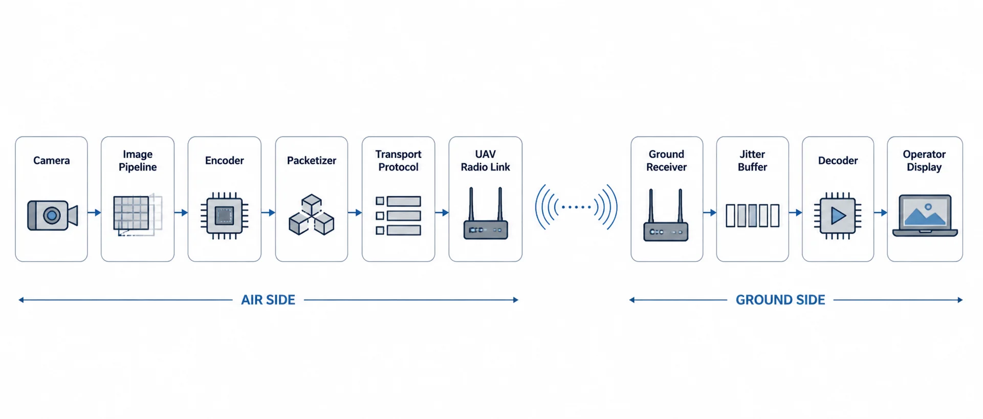
Between the camera sensor and the operator’s screen, there is a complete video pipeline:
Camera
→ Image pipeline
→ Encoder
→ Packetizer
→ Transport protocol
→ Radio link
→ Receiver
→ Jitter buffer
→ Decoder
→ Display
Every stage affects quality, delay, reliability, and range.
For drone companies, video-link engineering is often misunderstood because the radio is only one part of the problem. A strong UAV radio link can still produce poor video if the encoder, bitrate, protocol, or buffering strategy is wrong. Similarly, a well-encoded stream can fail if the transport protocol reacts badly to packet loss or link variation.
This article explains how UAVs send video over radio links, with a focus on codecs, latency, bitrate planning, and transport protocols such as RTSP, RTP/UDP, TCP, SRT, and WebRTC.
1. Why UAV video is different from normal video streaming
Streaming video from a UAV is different from streaming video over a wired network or the public internet.
A UAV radio link has changing conditions:
- distance changes during flight
- aircraft orientation changes
- antenna polarization may change
- line-of-sight may partially degrade
- packet loss can occur suddenly
- throughput can vary with range
- interference can appear unexpectedly
- retransmissions may increase latency
- onboard compute power may be limited
- power and thermal budgets are constrained
In normal video streaming, buffering is acceptable. A movie stream can buffer several seconds of data and still be considered good.
In UAV video, too much buffering is a problem.
The operator may need to make decisions based on the video feed. For inspection, surveillance, payload control, or teleoperation, the video must be fresh enough to be useful.
So UAV video-link design is always a trade-off between:
| Requirement | Engineering pressure |
|---|---|
| High image quality | Needs higher bitrate |
| Low latency | Needs less buffering and faster encoding |
| Long range | Needs lower bitrate and stronger link margin |
| Reliability | May need retransmission or buffering |
| Smooth playback | Needs jitter buffer |
| Telemetry protection | Video must not consume the full link |
| Low power | Limits encoder and compute choices |
There is no single “best” video protocol. The correct choice depends on the mission.
2. The UAV video pipeline
A typical UAV video system contains these stages:
| Stage | Role | Example |
|---|---|---|
| Camera sensor | Captures raw frames | USB camera, CSI camera, IP camera |
| Image pipeline | Converts sensor data | ISP, color conversion, scaling |
| Encoder | Compresses video | H.264, H.265 |
| Packetizer | Packs encoded frames into network packets | RTP, MPEG-TS, custom framing |
| Transport protocol | Moves packets over network | UDP, TCP, SRT, WebRTC |
| Radio link | Carries IP or packet data | UAV data link |
| Receiver | Accepts packets on ground side | Laptop, ground unit, GCS |
| Jitter buffer | Absorbs packet timing variation | Player/network buffer |
| Decoder | Decompresses video | CPU/GPU decoder |
| Display | Shows video | GCS, browser, video viewer |
A problem in any one of these stages can affect the final video.
For example:
- a high-bitrate encoder can overload the radio link
- a large jitter buffer can make video smooth but delayed
- TCP can avoid packet loss but cause stalls
- UDP can keep latency low but may show artifacts under packet loss
- SRT can recover lost packets but adds delay
- WebRTC can be convenient for dashboards but needs a more complex pipeline
3. Codec selection: H.264 vs H.265
The codec determines how raw video is compressed before transmission.
The most common UAV video codecs are:
- H.264 / AVC
- H.265 / HEVC
H.264
H.264 is widely supported and still the safest choice for many UAV systems.
Benefits:
- works with most IP cameras
- supported by many hardware encoders
- easy to decode on laptops and embedded systems
- compatible with RTSP, RTP, SRT, WebRTC, and many players
- lower compatibility risk
Trade-offs:
- needs more bitrate than H.265 for the same visual quality
- less efficient at very low bitrates
- may require higher bandwidth for 1080p or 4K video
H.265
H.265 provides better compression than H.264.
Benefits:
- lower bitrate for similar visual quality
- useful for bandwidth-limited links
- better for higher-resolution streams
- can reduce radio-link load
Trade-offs:
- higher encoding and decoding complexity
- compatibility issues with some browsers and players
- more CPU/GPU requirement
- licensing/support differences across devices
- may add latency depending on encoder settings
Practical comparison
| Codec | Strength | Trade-off | Good for |
|---|---|---|---|
| H.264 | Compatibility and lower complexity | Higher bitrate | General UAV video, IP cameras, GCS viewing |
| H.265 | Better compression | Higher compute and compatibility burden | Bandwidth-limited HD video, longer range, high-resolution payloads |
For most UAV teams, H.264 is the best starting point. H.265 becomes attractive when bandwidth is limited and the full system supports it reliably.
4. Resolution, frame rate, and bitrate planning
Video bitrate is usually the largest traffic load on the UAV radio link.
Typical practical planning values:
| Video mode | Practical bitrate range |
|---|---|
| 480p monitoring | 0.8–2 Mbps |
| 720p 30 FPS H.264 | 2–5 Mbps |
| 720p 30 FPS H.265 | 1.5–4 Mbps |
| 1080p 30 FPS H.264 | 4–12 Mbps |
| 1080p 30 FPS H.265 | 3–8 Mbps |
| 1080p 60 FPS H.264 | 8–20 Mbps |
| 4K monitoring | 15–40 Mbps |
A common mistake is to configure the video stream for bench-test quality instead of field reliability.
For example, 1080p at 15 Mbps may look excellent at short range. But when the UAV moves farther away, turns, or experiences packet loss, the link may not sustain that bitrate.
A better first field configuration:
| Use case | Starting video setting |
|---|---|
| Initial flight testing | 720p, 2–3 Mbps |
| General inspection | 720p/1080p, 3–6 Mbps |
| High-detail viewing | 1080p, 6–10 Mbps |
| Long-range operation | Lower bitrate or adaptive bitrate |
| Teleoperation | Lower resolution/bitrate with low-latency encoder settings |
For UAV operations, stable video is usually better than maximum video quality.
5. Encoder settings that affect latency
The video codec is important, but encoder settings matter just as much.
Important settings include:
| Setting | Effect |
|---|---|
| Bitrate | Controls bandwidth usage |
| CBR / VBR | Controls how predictable the bitrate is |
| GOP size | Affects recovery and compression efficiency |
| Keyframe interval | Affects seek/recovery behavior |
| B-frames | Improve compression but can add delay |
| Encoder preset | Balances quality, compute, and latency |
| Profile/level | Affects compatibility |
| Rate control | Affects burstiness and stability |
| Slice size / packetization | Affects packet loss behavior |
CBR vs VBR
CBR means constant bitrate. VBR means variable bitrate.
| Mode | Benefit | Risk |
|---|---|---|
| CBR | Predictable radio load | Quality varies with scene complexity |
| VBR | Better quality at same average bitrate | Can create bitrate spikes |
| Capped VBR | Better quality with a ceiling | Needs careful tuning |
For UAV radio links, CBR or capped VBR is usually safer than uncontrolled VBR.
GOP and keyframes
A GOP is a group of pictures. It defines how often full reference frames are inserted.
If keyframes are too far apart, recovery after packet loss can be slow. If keyframes are too frequent, bitrate increases.
Typical starting points:
| Frame rate | Keyframe interval |
|---|---|
| 30 FPS | 1–2 seconds, 30–60 frames |
| 60 FPS | 1–2 seconds, 60–120 frames |
For lossy UAV links, shorter keyframe intervals can help recovery, but they also consume more bandwidth.
B-frames
B-frames improve compression but can increase latency because frames may need to be reordered.
For low-latency UAV video, many teams disable B-frames.
6. Latency budget: where the delay comes from
Latency is not only a radio problem.
A typical UAV video latency budget may look like this:
| Stage | Typical delay |
|---|---|
| Camera exposure | 5–33 ms |
| Image processing / ISP | 5–50 ms |
| Encoding | 20–150 ms |
| Packetization | 5–20 ms |
| OS/network queue | 5–30 ms |
| Radio transmission | 5–50 ms |
| Retransmission / jitter | 0–200+ ms |
| Jitter buffer | 20–300 ms |
| Decoding | 10–80 ms |
| Display | 16–50 ms |
Typical end-to-end latency:
| Workflow | Realistic latency |
|---|---|
| Raw RTP/UDP low-latency pipeline | 80–200 ms |
| RTSP over UDP | 150–400 ms |
| RTSP over TCP | 300 ms–2 s+ |
| SRT | 200 ms–1 s depending on latency window |
| WebRTC | 150–500 ms depending on implementation |
| Heavily buffered video | 1 s+ |
The important point is that a “low-latency radio” does not automatically produce low-latency video. The encoder, transport protocol, and player buffer often dominate total delay.
7. Transport protocols: what actually carries the video?
Once video is compressed, it must be transported over the UAV radio link.
Common options include:
- RTSP / RTP
- RTP over UDP
- MPEG-TS over UDP
- MPEG-TS over SRT
- RTSP over TCP
- WebRTC
- custom UDP transport
Each option behaves differently under packet loss, jitter, and throughput variation.
8. RTSP and RTP
RTSP is common in IP cameras.
Strictly speaking, RTSP is a session/control protocol. The media itself is usually carried using RTP.
RTSP can run in different modes:
| Mode | Behavior |
|---|---|
| RTSP/RTP over UDP | Lower latency, packet loss possible |
| RTSP interleaved over TCP | More reliable delivery, higher risk of stalls |
| RTSP through proxy/relay | Useful for distribution or protocol conversion |
When RTSP is useful
RTSP is useful when:
- the camera is an IP camera
- compatibility matters
- the ground software already supports RTSP
- multiple tools need to view the stream
- the system is for inspection or monitoring
RTSP limitations
RTSP may not be ideal when:
- ultra-low latency is required
- packet loss is frequent
- the player uses a large default buffer
- the stream is forced over TCP
- the radio link has variable throughput
Many RTSP players buffer more than expected. This can make video smooth but delayed.
For UAV usage, RTSP should be tested with actual player buffer settings, not only whether the stream opens.
9. RTP or MPEG-TS over UDP
UDP is often used when low latency is more important than perfect delivery.
With UDP:
- there is no automatic retransmission
- lost packets are not resent
- latency can remain low
- video may show artifacts if packets are lost
- the application must tolerate loss
Common UDP video workflows:
| Workflow | Description |
|---|---|
| RTP over UDP | Common for real-time media |
| MPEG-TS over UDP | Simple transport stream over UDP |
| Custom UDP framing | Used in custom GCS or embedded systems |
Why UDP is popular for UAV video
UDP is popular because it does not stall the stream waiting for lost packets.
This is useful for real-time video. A slightly corrupted frame is often better than a delayed perfect frame.
UDP risks
UDP can fail badly if not controlled:
- no congestion control by default
- can overwhelm the link
- high bitrate can starve telemetry
- packet loss can create visual artifacts
- large packets may fragment
- no built-in recovery
For UAV links, UDP video should be bitrate-limited and monitored.
10. TCP video over UAV radio links
TCP is reliable, but reliability comes with a cost.
TCP guarantees ordered delivery. If one packet is lost, later packets may wait until the missing packet is retransmitted.
This can cause:
- video stalls
- sudden latency buildup
- bursty playback
- congestion-control slowdowns
- delayed recovery after packet loss
TCP can be useful for configuration, dashboards, file transfer, and control APIs. But for real-time UAV video, TCP can behave poorly when the wireless link becomes lossy.
A common issue:
Wireless packet loss
→ TCP retransmission
→ congestion window reduction
→ lower throughput
→ video buffer grows
→ operator sees delayed or frozen video
This is why RTSP over TCP may look reliable during bench testing but become delayed or unstable in the field.
11. SRT for UAV video
SRT stands for Secure Reliable Transport.
SRT is designed for video transport over unreliable networks. It uses packet recovery and configurable latency windows.
Why SRT is useful
SRT can help when:
- the link has occasional packet loss
- video quality matters
- some added delay is acceptable
- the operator needs smoother monitoring
- the network path is not perfectly stable
SRT trade-off
SRT can recover lost packets, but it needs time to do so.
The SRT latency window controls how much time the receiver has to recover missing packets.
| SRT latency setting | Behavior |
|---|---|
| Low latency | Lower delay, less recovery time |
| Medium latency | Balanced |
| High latency | Better recovery, more delay |
Typical SRT latency values may range from 120 ms to 1000 ms depending on the use case.
For UAVs:
| Use case | SRT suitability |
|---|---|
| Inspection video | Good |
| Ground monitoring | Good |
| Recording stream | Good |
| Teleoperation | Depends on latency |
| FPV-style flying | Usually not ideal |
| High-loss environment | Useful, but bitrate must be controlled |
SRT is often a good option when the goal is reliable viewing rather than minimum possible latency.
12. WebRTC for UAV video
WebRTC is widely used for low-latency browser-based video.
It can be attractive for UAV systems because it allows video to be viewed in a browser without a separate native player.
WebRTC benefits
- browser support
- low-latency design
- adaptive jitter buffering
- real-time media focus
- can support interactive dashboards
- works well with web-based operator interfaces
WebRTC complexity
WebRTC is more complex than raw UDP or RTSP.
It may require:
- signaling server
- ICE/STUN/TURN configuration
- media server or gateway
- codec compatibility planning
- browser support validation
- careful NAT/firewall handling
- monitoring of jitter and packet loss
For local UAV radio links, NAT traversal may be less important than in internet streaming, but WebRTC still has more moving parts.
When WebRTC is useful
WebRTC is useful when:
- the operator interface is browser-based
- video must be integrated into a web dashboard
- latency should be reasonably low
- the system has enough compute to handle the pipeline
- there is a local media server or gateway
13. Protocol comparison
| Transport | Latency | Loss behavior | Complexity | Best use |
|---|---|---|---|---|
| RTP/UDP | Very low | Lost packets are dropped | Medium | Low-latency controlled pipelines |
| MPEG-TS/UDP | Low | Lost packets are dropped | Low/medium | Simple field video |
| RTSP over UDP | Low/medium | Packet loss may create artifacts | Low | IP camera workflows |
| RTSP over TCP | Medium/high | Retransmits but may stall | Low | Stable networks, compatibility |
| SRT | Medium | Recovers loss within latency window | Medium | Reliable field monitoring |
| WebRTC | Low/medium | Adaptive, implementation-dependent | High | Browser dashboards, interactive viewing |
| Custom UDP | Very low | Application-defined | High | Purpose-built systems |
There is no universal winner. The best protocol depends on the mission.
14. Recommended protocol by UAV use case
| Use case | Recommended approach |
|---|---|
| IP camera compatibility | RTSP, preferably RTP over UDP where possible |
| Lowest latency video | RTP/UDP or custom UDP pipeline |
| General inspection UAV | RTSP/UDP or SRT |
| Long-range monitoring | Lower bitrate + SRT or conservative RTP/UDP |
| Browser-based dashboard | WebRTC |
| Recording and review | RTSP, SRT, or local onboard recording |
| Teleoperation | RTP/UDP or carefully tuned WebRTC |
| Unstable radio link | SRT with controlled latency window |
| Development testing | RTSP for simplicity, then optimize |
A practical engineering approach is to start simple, then optimize.
Step 1: Get IP camera RTSP working
Step 2: Measure latency and packet loss
Step 3: Tune bitrate and GOP
Step 4: Test RTSP/UDP vs RTSP/TCP
Step 5: Evaluate SRT or WebRTC if needed
Step 6: Add telemetry protection/QoS
15. Packet loss and what the operator sees
Different protocols fail differently.
| Failure mode | Operator experience |
|---|---|
| UDP packet loss | Artifacts, blockiness, frame corruption |
| TCP packet loss | Freezes, stalls, delayed playback |
| SRT recovery delay | Smoother stream but added latency |
| Buffer too small | Jitter, frame drops |
| Buffer too large | Smooth but delayed video |
| Bitrate too high | Increasing packet loss and instability |
| Keyframes too sparse | Slow recovery after corruption |
For UAV video, graceful degradation is important.
A good system should prefer:
Slightly lower image quality
over
delayed or frozen video
16. Telemetry must not compete with video
Video can consume almost all available bandwidth if left uncontrolled.
Telemetry and command data are usually much smaller, but they are more critical.
A basic traffic priority strategy:
| Priority | Traffic |
|---|---|
| 1 | Command/control |
| 2 | Autopilot telemetry |
| 3 | Payload safety/status |
| 4 | Live video |
| 5 | Web dashboard/diagnostics |
| 6 | File transfer/logs |
Practical recommendations:
- cap video bitrate
- avoid uncontrolled VBR video
- avoid file downloads during flight
- do not let video saturate the link
- use separate ports/flows for telemetry and video
- monitor packet loss and jitter
- reduce video bitrate when operating at range
- protect command and telemetry traffic first
For a UAV system, losing some video quality is acceptable. Losing reliable telemetry is much more serious.
17. Practical bandwidth examples
Example 1: Basic inspection UAV
| Traffic | Bandwidth |
|---|---|
| 720p H.264 video | 3 Mbps |
| MAVLink telemetry | 100 kbps |
| Payload status | 50 kbps |
| Dashboard/API | 200 kbps |
| Margin | 3 Mbps |
| Total planned | ~6.35 Mbps |
Example 2: 1080p monitoring UAV
| Traffic | Bandwidth |
|---|---|
| 1080p H.264 video | 6 Mbps |
| MAVLink telemetry | 200 kbps |
| Payload control/status | 100 kbps |
| SSH/diagnostics | 500 kbps average |
| Margin | 5 Mbps |
| Total planned | ~11.8 Mbps |
Example 3: High-quality video payload
| Traffic | Bandwidth |
|---|---|
| 1080p high-quality video | 12 Mbps |
| Telemetry | 200 kbps |
| Payload metadata | 500 kbps |
| Dashboard | 500 kbps |
| Margin | 8 Mbps |
| Total planned | ~21.2 Mbps |
This requires stronger link margin and should be tested carefully at range.
18. Practical GStreamer-style workflows
The exact command depends on camera, encoder, platform, and receiver. The examples below are conceptual starting points.
H.264 RTP over UDP
Good for low-latency controlled networks.
# Sender concept
gst-launch-1.0 -v \\
  v4l2src device=/dev/video0 ! \\
  video/x-raw,width=1280,height=720,framerate=30/1 ! \\
  videoconvert ! \\
  x264enc tune=zerolatency bitrate=3000 speed-preset=ultrafast key-int-max=30 ! \\
  rtph264pay config-interval=1 pt=96 ! \\
  udpsink host=<GROUND_IP> port=5600
# Receiver concept
gst-launch-1.0 -v \\
udpsrc port=5600 caps="application/x-rtp,media=video,encoding-name=H264,payload=96" ! \\
rtph264depay ! \\
avdec_h264 ! \\
autovideosink sync=falseMPEG-TS over UDP
Simple and common for field testing.
# Sender concept
gst-launch-1.0 -v \\
  v4l2src device=/dev/video0 ! \\
  video/x-raw,width=1280,height=720,framerate=30/1 ! \\
  videoconvert ! \\
  x264enc tune=zerolatency bitrate=3000 speed-preset=ultrafast key-int-max=30 ! \\
  h264parse ! \\
  mpegtsmux ! \\
  udpsink host=<GROUND_IP> port=5601
MPEG-TS over SRT
Useful when some packet recovery is needed.
# Sender concept
gst-launch-1.0 -v \\
  v4l2src device=/dev/video0 ! \\
  video/x-raw,width=1280,height=720,framerate=30/1 ! \\
  videoconvert ! \\
  x264enc tune=zerolatency bitrate=4000 speed-preset=veryfast key-int-max=60 ! \\
  h264parse ! \\
  mpegtsmux ! \\
  srtsink uri="srt://<GROUND_IP>:8890?mode=caller&latency=200"
These examples should be treated as starting points. Hardware encoders are usually preferred for embedded UAV systems when available.
19. Common mistakes in UAV video-link design
Mistake 1: Planning around peak PHY rate
A radio may advertise a high PHY rate, but field throughput at range can be much lower.
Plan around stable application throughput, not peak PHY rate.
Mistake 2: Setting video bitrate too high
High bitrate may look good nearby but fail at range.
Start with conservative bitrate and increase only after field validation.
Mistake 3: Using large player buffers
Large buffers make video smooth but delayed.
Always measure end-to-end latency, not only playback smoothness.
Mistake 4: Forcing TCP for real-time video
TCP may avoid packet loss but can cause stalls and latency buildup over wireless links.
Mistake 5: Ignoring telemetry priority
Video should not consume the full link.
Telemetry and command traffic must be protected.
Mistake 6: Not testing during aircraft movement
Ground tests do not capture antenna orientation changes, aircraft body blockage, vibration, and turning behavior.
Mistake 7: Assuming one protocol works for every mission
RTSP, UDP, SRT, and WebRTC are tools. The mission decides which tool is appropriate.
20. Suggested architecture for a mixed UAV video and telemetry link
A practical architecture may look like this:
This architecture lets video, telemetry, serial data, and IP traffic share the same radio link, as long as bandwidth and priority are controlled.
21. Where CY-2 fits
CY-2 is designed as a compact UAV/UGV data link for mixed platform traffic: video, telemetry, UART, and IP data between the vehicle side and the operator side.
For video workflows, CY-2 can support IP-based communication paths such as:
- IP camera access
- USB camera workflow through onboard processing
- RTSP/UDP/TCP video transport depending on configuration
- ground-side video viewing
- onboard computer access
- web dashboard and diagnostics
- telemetry and video over the same link
The key engineering point is that the radio link should not be treated as “video only.” It should be planned as a mixed-data communication path where video is controlled, telemetry is protected, and IP access remains available for diagnostics and integration.
22. FAQ
What is the best protocol for UAV video?
There is no single best protocol. RTP/UDP is good for low latency, RTSP is good for IP camera compatibility, SRT is good for lossy links with some recovery, and WebRTC is good for browser-based low-latency dashboards.
Is RTSP good for drone video?
Yes, RTSP is common and useful, especially with IP cameras. However, the actual latency depends on whether RTP uses UDP or TCP and how much buffering the player applies.
Is UDP better than TCP for UAV video?
For real-time video, UDP is often better because it avoids retransmission stalls. But UDP does not recover lost packets, so bitrate and link quality must be managed carefully.
When should SRT be used?
SRT is useful when the radio link has occasional packet loss and smoother video is more important than minimum latency. It is good for inspection, monitoring, and recording workflows.
Can WebRTC be used for UAV video?
Yes. WebRTC can be useful for browser-based operator interfaces and low-latency dashboards, but it requires a more complex pipeline than simple RTSP or UDP streaming.
What bitrate should I use for UAV video?
For early field tests, start with 720p at 2–3 Mbps or 1080p at 4–6 Mbps. Increase bitrate only after validating link stability at the required range.
Why does my drone video freeze even though the radio is connected?
The link may be connected but not providing enough stable throughput. TCP retransmissions, high bitrate, packet loss, large buffers, or weak signal margin can cause video freezing.
Should telemetry and video use the same link?
They can share the same link if bandwidth and priority are managed. Video should be bitrate-limited so telemetry and command traffic remain reliable.
23. Conclusion
UAV video over radio links is a full system engineering problem.
The radio matters, but so do:
- codec choice
- bitrate
- frame rate
- encoder settings
- keyframe interval
- transport protocol
- packet loss behavior
- jitter buffer
- decoder performance
- telemetry prioritization
- link margin
For most UAV teams, the best approach is to start with a conservative video configuration, measure latency and packet loss, protect telemetry, and then optimize the transport protocol based on the mission.
A good UAV video link is not the one with the highest advertised bitrate. It is the one that delivers usable video at the required range, with acceptable latency, while keeping telemetry and control traffic reliable.