Blogs
LOS Is Not Just "Can I See It?": UAV Radio Link Engineering Explained
Published
Learn why UAV radio LOS is more than visual line-of-sight, and how bandwidth, latency, Fresnel zone, antenna gain, and link budget affect drone data links.
Article
Overview.
Visual line-of-sight is not the same as RF line-of-sight. This technical guide explains how bandwidth, latency, link budget, antenna gain, free-space path loss, and Fresnel zone clearance affect UAV radio link performance — and how to design a link around realistic mission numbers rather than datasheet peaks.
1. Start with the mission
A UAV radio link should not be selected by looking at peak data rate or advertised range alone.
A useful communication link has to satisfy the mission requirement:
- How far should the vehicle operate?
- What video resolution and bitrate are required?
- Is telemetry safety-critical?
- Is the payload controlled over UART, Ethernet, or IP?
- Does the operator need access to an onboard computer?
- What latency is acceptable?
- Is the link point-to-point, point-to-multipoint, or multi-node?
- Is the environment open field, urban, mountainous, maritime, or industrial?
- What antennas can physically fit on the UAV?
- What is the available power budget?
A small UAV doing 1 km inspection with 720p monitoring has a very different communication requirement from a long-range platform sending 1080p video, telemetry, and payload data over 5–10 km.
2. Start with the traffic budget
Before calculating range, calculate the data requirement.
A typical UAV data link may carry:
| Traffic type | Direction | Typical bandwidth | Latency sensitivity |
|---|---|---|---|
| MAVLink telemetry | Bidirectional | 50–300 kbps | High |
| Command/control messages | Ground → air | 5–100 kbps | Very high |
| Payload status | Air → ground | 10–500 kbps | Medium |
| 720p H.264 video | Air → ground | 2–5 Mbps | Medium/high |
| 1080p H.264 video | Air → ground | 4–12 Mbps | Medium/high |
| 1080p H.265 video | Air → ground | 3–8 Mbps | Medium/high |
| Web dashboard | Bidirectional | 100 kbps–1 Mbps average | Medium |
| SSH/diagnostics | Bidirectional | Bursty, usually <1 Mbps | Low/medium |
| Log/file transfer | Air → ground | Bursty, can be large | Low |
A practical data budget should include margin:
| Stream | Planned bandwidth |
|---|---|
| 1080p H.264 video | 6.0 Mbps |
| MAVLink telemetry | 0.2 Mbps |
| Payload control/status | 0.1 Mbps |
| Web dashboard/API | 0.5 Mbps |
| SSH/diagnostics | 0.5 Mbps |
| Protocol and operating margin | 5.0 Mbps |
| Total planning budget | 12.3 Mbps |
This does not mean the radio should advertise "12 Mbps." It means the link should provide at least 12 Mbps of stable application throughput under the expected field condition.
3. PHY rate is not application throughput
Radio datasheets often mention PHY rate. For example, an 802.11ac 2×2 radio may support a peak PHY rate of up to 867 Mbps under ideal conditions.
But PHY rate is not the same as usable throughput.
Application throughput is reduced by:
- MAC overhead
- TCP/UDP/IP overhead
- encryption overhead
- channel contention
- retransmissions
- modulation and coding changes
- packet loss
- antenna mismatch
- multipath
- aircraft orientation
- distance
- RF noise
- CPU and interface limits
A realistic planning table:
| Link condition | Application throughput planning |
|---|---|
| Short range, strong signal, clean channel | 50–200+ Mbps may be possible |
| Moderate range field link | 10–50 Mbps is a safer planning range |
| Longer range LOS link | 2–20 Mbps depending on link margin |
| Edge-of-range operation | Preserve telemetry; reduce video bitrate |
For UAV links, stable throughput matters more than peak throughput.
4. Video bitrate planning
Video is usually the largest part of the UAV data budget.
The required bitrate depends on resolution, frame rate, codec, scene complexity, encoder settings, GOP/keyframe interval, CBR/VBR mode, latency target, and error recovery behavior.
| Video mode | Practical bitrate range |
|---|---|
| 480p monitoring | 0.8–2 Mbps |
| 720p 30 FPS H.264 | 2–5 Mbps |
| 720p 30 FPS H.265 | 1.5–4 Mbps |
| 1080p 30 FPS H.264 | 4–12 Mbps |
| 1080p 30 FPS H.265 | 3–8 Mbps |
| 1080p 60 FPS H.264 | 8–20 Mbps |
| 4K monitoring | 15–40 Mbps |
For UAV field use, bitrate should be selected based on link margin, not only image quality.
A common mistake is to test video at 1080p 15–20 Mbps near the ground station, then expect it to remain stable at several kilometers.
| Use case | Recommended starting point |
|---|---|
| Early flight testing | 720p, 2–3 Mbps |
| Stable inspection video | 720p/1080p, 3–6 Mbps |
| High-detail monitoring | 1080p, 6–10 Mbps |
| Long-range operation | Adaptive bitrate or conservative fixed bitrate |
| Teleoperation | Prefer lower latency over maximum resolution |
5. Latency is a system-level number
Radio latency is only one part of the total video/control latency.
End-to-end latency includes the entire chain:
Camera exposure
→ image pipeline
→ encoder
→ packetization
→ operating system queues
→ wireless radio
→ network jitter buffer
→ decoder
→ display| Stage | Typical delay |
|---|---|
| Camera exposure | 5–33 ms |
| Image processing pipeline | 5–50 ms |
| Video encoding | 20–150 ms |
| Packetization/network queue | 5–30 ms |
| Wireless link | 5–50 ms |
| Retransmission/jitter | 0–200+ ms |
| Decoder | 10–80 ms |
| Display | 16–50 ms |
| Workflow | Realistic latency |
|---|---|
| UART telemetry only | 10–100 ms |
| IP telemetry | 20–150 ms |
| Low-latency 720p video | 80–200 ms |
| Normal 1080p stream | 150–400 ms |
| Buffered RTSP/SRT/WebRTC stream | 200 ms–1 s+ |
| Poor link with retransmissions | Highly variable |
For UAV operations, latency should be considered relative to the task:
| Task | Latency tolerance |
|---|---|
| Autopilot telemetry monitoring | 100–500 ms usually acceptable |
| Manual payload/gimbal control | 100–300 ms preferred |
| FPV-style piloting | As low as possible |
| Inspection/surveillance | 200–500 ms often usable |
| AI monitoring or recording | Latency may be less important than stability |
6. Link budget: the core RF calculation
A radio link budget estimates whether enough signal power reaches the receiver.
The simplified equation:
Received Power =
  Tx Power
+ Tx Antenna Gain
- Tx Cable Loss
- Free Space Path Loss
+ Rx Antenna Gain
- Rx Cable Loss
In dB form:
Prx(dBm) = Ptx(dBm) + Gtx(dBi) - Ltx(dB) - FSPL(dB) + Grx(dBi) - Lrx(dB)| Term | Meaning |
|---|---|
Prx | Received power at receiver input |
Ptx | Transmit power |
Gtx | Transmit antenna gain |
Ltx | Transmit-side cable/connector loss |
FSPL | Free-space path loss |
Grx | Receive antenna gain |
Lrx | Receive-side cable/connector loss |
The link works only if received power is above receiver sensitivity by a useful margin:
Link Margin = Received Power - Receiver SensitivityExample:
| Parameter | Value |
|---|---|
| Transmit power | 29 dBm |
| Tx antenna gain | 3 dBi |
| Tx cable loss | 1 dB |
| Path loss | 121.7 dB |
| Rx antenna gain | 12 dBi |
| Rx cable loss | 1 dB |
| Received power | −79.7 dBm |
If receiver sensitivity for the selected modulation is −88 dBm:
Link Margin = −79.7 − (−88) = 8.3 dBAn 8 dB margin may work, but it is not comfortable for a moving UAV. Aircraft attitude, antenna nulls, multipath, and interference can quickly consume margin.
7. Free-space path loss at 5 GHz
Free-space path loss is the signal loss caused by spreading of electromagnetic energy over distance.
The commonly used formula:
FSPL(dB) = 32.44 + 20·log₁₀(distance_km) + 20·log₁₀(frequency_MHz)For a 5.8 GHz link:
| Distance | FSPL at 5.8 GHz |
|---|---|
| 0.5 km | ≈101.7 dB |
| 1 km | ≈107.7 dB |
| 3 km | ≈117.2 dB |
| 5 km | ≈121.7 dB |
| 10 km | ≈127.7 dB |
| 20 km | ≈133.7 dB |
Two important observations:
- Every doubling of distance adds about 6 dB of path loss.
- Higher frequencies have higher path loss for the same distance.
This does not mean 5 GHz cannot be used for UAV links. It means antenna planning, channel selection, and link margin are important.
8. LOS is not just "can I see it?"
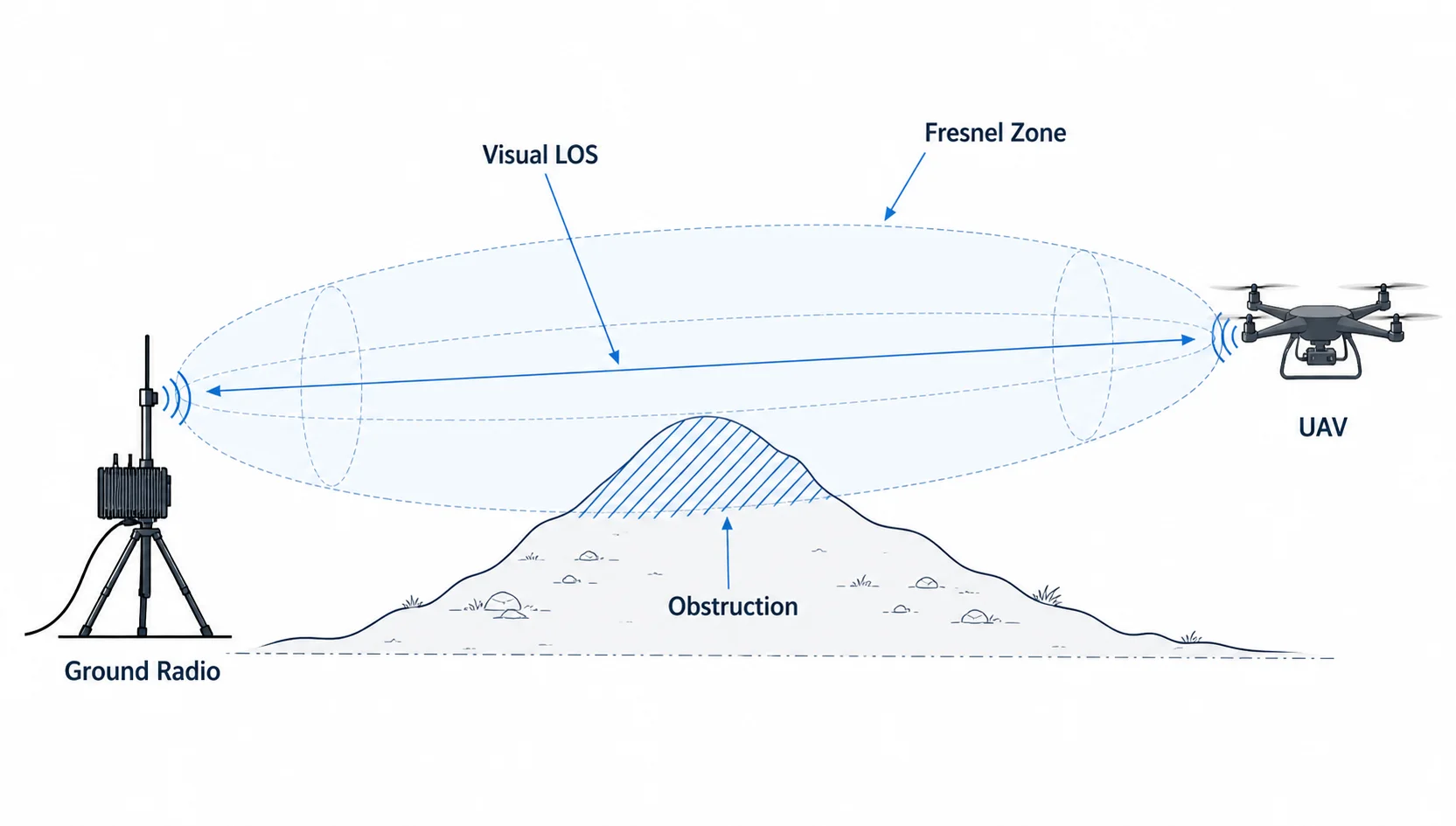
Visual line-of-sight and RF line-of-sight are not the same thing.
At radio frequencies, energy does not travel as an infinitely thin beam. The useful radio path occupies an ellipsoidal region around the straight line between transmitter and receiver. This region is called the Fresnel zone.
Even if the drone is visible, objects near the path can disturb the signal — ground, terrain slopes, trees, rocks, buildings, the aircraft body, the carbon-fiber frame, the battery pack, or the payload enclosure.

The first Fresnel zone radius can be approximated by:
r = 17.32 × √((d1 × d2) / (fGHz × D))| Symbol | Meaning |
|---|---|
r | Fresnel zone radius in meters |
d1 | Distance from transmitter to obstruction in km |
d2 | Distance from obstruction to receiver in km |
D | Total link distance in km |
fGHz | Frequency in GHz |
At the midpoint of the link, d1 = d2 = D/2.
For 5.8 GHz, approximate midpoint first Fresnel zone radius:
| Link distance | Midpoint Fresnel radius |
|---|---|
| 1 km | ≈3.6 m |
| 3 km | ≈6.2 m |
| 5 km | ≈8.0 m |
| 10 km | ≈11.4 m |
| 20 km | ≈16.1 m |
A common rule is to keep at least 60% of the first Fresnel zone clear.
So at 5 km, if the midpoint Fresnel radius is about 8 m, roughly 5 m of clearance around the path is desirable.
This is why a UAV can be visually visible but still have a weak radio link.
9. Antenna gain, beamwidth, and practical trade-offs
Antenna gain is not free power. It reshapes the radiation pattern — a higher-gain antenna concentrates energy in a narrower direction.
| Antenna type | Typical gain | Strength | Limitation |
|---|---|---|---|
| Small omni | 2–3 dBi | Easy mounting, wide coverage | Limited range |
| Higher-gain omni | 5–9 dBi | Better horizontal range | Narrower vertical beam |
| Patch antenna | 8–14 dBi | Good ground-side directionality | Needs aiming |
| Sector antenna | 10–16 dBi | Covers a wider area | Larger size |
| Dish/grid | 18–30 dBi | Long range | Narrow beam, needs accurate pointing |
Air side
The UAV antenna should be lightweight, low-drag, mechanically stable, placed away from carbon fiber and batteries, and positioned to reduce blockage during turns and attitude changes.
Ground side
The ground antenna can be larger and higher gain because weight is less critical.
| Side | Antenna strategy |
|---|---|
| UAV side | 2–5 dBi omni or compact diversity antenna |
| Ground side | 8–14 dBi patch/sector antenna or higher-gain directional |
| Long-range setup | Ground-side mast, careful aiming, low-loss cable |
10. Cable loss matters at 5 GHz
At 5 GHz, RF cable loss can be significant. Thin coax over a long run reduces link budget quickly.
| Cable loss | Effect |
|---|---|
| 0.5 dB | Small |
| 1 dB | Acceptable but noticeable |
| 2 dB | Significant |
| 3 dB | Half the RF power lost |
| 6 dB | 75% power loss |
A 3 dB cable loss means half of the RF power is lost before reaching the antenna.
Keep RF cables short, use good-quality connectors, avoid sharp bends, secure cables against vibration, and place the radio close to the antenna where possible.
11. Channel bandwidth: range versus throughput
Wider channels can carry more data, but they need better signal quality and a cleaner spectrum.
| Channel bandwidth | Advantage | Risk |
|---|---|---|
| 10 MHz | Better robustness, lower noise bandwidth | Lower throughput |
| 20 MHz | Good balance | Moderate throughput |
| 40 MHz | Higher throughput | Needs cleaner RF |
| 80 MHz | Maximum peak rate | Not ideal for long-range or noisy field use |
Noise power increases with bandwidth. Thermal noise is approximated by:
Noise Floor(dBm) = −174 + 10·log₁₀(B) + NF| Symbol | Meaning |
|---|---|
B | Bandwidth in Hz |
NF | Receiver noise figure in dB |
Example with NF = 5 dB:
| Channel bandwidth | Approx. noise floor |
|---|---|
| 10 MHz | −99 dBm |
| 20 MHz | −96 dBm |
| 40 MHz | −93 dBm |
| 80 MHz | −90 dBm |
Doubling bandwidth increases noise by about 3 dB. This means 80 MHz mode may show high peak rate at short range, but 20 MHz or 40 MHz may be more practical for field operation.
12. Receiver sensitivity and modulation
Modern radios change modulation and coding rate depending on signal quality.
| Signal condition | Behavior |
|---|---|
| Strong signal | Higher modulation, high throughput |
| Medium signal | Lower modulation, stable moderate throughput |
| Weak signal | Robust mode, low throughput |
| Very weak signal | Packet loss, retransmissions, link drop |
This is why range and throughput are connected. The link may still exist at long range, but the usable throughput may be much lower.
For UAV data links, the important question is not "is the link connected?" — it is "does the link provide enough stable throughput and low enough latency for the mission?"
13. Link budget example for a 5.8 GHz UAV link
A simplified 5 km example:
| Parameter | Value |
|---|---|
| Frequency | 5.8 GHz |
| Distance | 5 km |
| Transmit power | 29 dBm |
| UAV antenna gain | 3 dBi |
| UAV cable loss | 1 dB |
| Ground antenna gain | 12 dBi |
| Ground cable loss | 1 dB |
| FSPL at 5 km | 121.7 dB |
Received power:
Prx = 29 + 3 − 1 − 121.7 + 12 − 1
Prx = −79.7 dBm
Comparing to receiver sensitivity:
| Receiver sensitivity | Link margin |
|---|---|
| −90 dBm | 10.3 dB |
| −88 dBm | 8.3 dB |
| −85 dBm | 5.3 dB |
| −82 dBm | 2.3 dB |
| −80 dBm | 0.3 dB |
At high data rate, receiver sensitivity may be worse. At lower data rate, sensitivity is usually better. The same physical link may support drone telemetry reliably while failing to sustain high-bitrate video.
14. Why UAV orientation affects link quality
A UAV is not a fixed tower. It moves, turns, vibrates, pitches, rolls, and yaws.
This affects antenna polarization, antenna pattern, body blockage, multipath, MIMO performance, cable stress, and connector stability.
During a turn, the aircraft body or battery may partially block the antenna. If the antenna has a null in that direction, the received signal can drop suddenly.
This is why flight testing is different from ground testing. A radio link that looks stable when both units are sitting on a table may behave very differently when the UAV banks during flight.
15. MIMO and diversity
A 2×2 MIMO radio uses two transmit/receive chains, which can improve throughput, diversity, multipath handling, and link stability — but only when the antenna system is designed properly.
Important points:
- use both antenna ports
- maintain physical separation where possible
- avoid placing both antennas in the same null region
- consider polarization diversity
- avoid blocking both antennas with the same airframe component
- test the link while the UAV changes orientation
For compact UAVs, MIMO antenna placement is often a mechanical integration problem as much as an RF problem.
16. QoS: protect telemetry before video
In a mixed-data UAV link, video can easily dominate bandwidth. If video consumes the entire link, telemetry and command traffic may suffer.
A good configuration should prioritize:
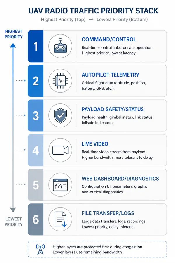
- command/control
- telemetry
- payload safety/status data
- video stream
- dashboards and diagnostics
- file transfer/log download
Practical strategies:
- set video bitrate limits
- use CBR or capped VBR
- avoid uncontrolled high-bitrate streams
- separate traffic classes where possible
- prioritize telemetry packets
- avoid large file transfers during flight
- reduce video bitrate at range
- monitor packet loss and latency
For many UAV missions, a slightly lower-quality video stream with stable telemetry is more useful than high-quality video with delayed aircraft state.
17. Range planning should include fade margin
A static link budget is only the starting point. Real field links need fade margin to account for multipath, aircraft rotation, temporary obstruction, atmospheric variation, antenna mismatch, polarization mismatch, connector aging, RF noise, and installation differences.
| Link margin | Interpretation |
|---|---|
| 0–3 dB | Unstable, edge-of-link |
| 3–6 dB | May work but fragile |
| 6–10 dB | Usable with caution |
| 10–20 dB | Good practical margin |
| 20 dB+ | Strong margin |
For UAV operations, a margin of 10 dB or more is desirable when possible.
18. Field test methodology
A good UAV radio test should be progressive. Do not start with the maximum range claim.
Step 1: Bench test
Validate power stability, boot behavior, Ethernet connection, UART settings, video stream, telemetry flow, IP access, web dashboard, SSH/diagnostics, and thermal behavior.
Step 2: Short outdoor test
At 50–100 m, test antenna orientation, video latency, telemetry update rate, packet loss, and basic mobility.
Step 3: Medium range test
At 500 m to 1 km, test video stability, link recovery, aircraft turns, antenna blockage, RF noise, and telemetry continuity.
Step 4: Mission range test
At 3 km, 5 km, or target range, test required video bitrate, link margin, latency under load, packet loss during turns, Fresnel clearance, ground antenna height, and failure behavior.
Step 5: Edge-of-range test
Intentionally reduce margin to understand when video degrades, when telemetry becomes unstable, whether the link recovers automatically, whether bitrate adaptation is needed, and what the operator sees during degradation.
The goal is not only to prove the link works — it is to understand how it fails.
19. Practical configuration for a 5 GHz UAV/UGV data link
For a 5 GHz 2×2 MIMO UAV/UGV data link carrying video, telemetry, UART, and IP traffic, a practical starting configuration:
| Parameter | Practical starting point |
|---|---|
| Channel bandwidth | 20 MHz or 40 MHz |
| Video bitrate | 3–6 Mbps for early field testing |
| Video resolution | 720p or 1080p depending on margin |
| Telemetry | 50–300 kbps |
| UART baud rate | 57,600–921,600 depending on device |
| Ground antenna | Directional or elevated antenna preferred |
| UAV antenna | Lightweight dual antenna, properly separated |
| IP access | Use for diagnostics, avoid heavy transfers in flight |
| QoS | Prioritize telemetry and command |
| Testing | Increase distance gradually |
80 MHz channel operation can be useful at short range, but for longer range and field use, narrower channels may provide a more stable link.
20. Where CY-2 fits in this engineering discussion
CY-2 is a compact UAV/UGV radio link for mixed traffic: video, telemetry, UART, and IP data between a vehicle-side unit and a ground-side unit.
The engineering principles in this article apply directly to CY-2 deployments:
- do not plan only around peak PHY rate
- define a traffic budget before field testing
- keep telemetry protected
- use practical video bitrates
- choose antenna placement carefully
- treat 5 GHz as a high-bandwidth LOS link
- calculate link budget for the target range
- remember that LOS is not just visual visibility
- validate performance with real field tests
For drone companies, the value of an integrated link is not just that it can carry data — it is that it can carry the right mix of data reliably under realistic mission conditions.
21. Frequently asked questions
Is visual line-of-sight enough for UAV radio range?
No. Visual line-of-sight is helpful, but RF line-of-sight also depends on Fresnel zone clearance, antenna height, terrain, frequency, and link margin.
Why does a drone radio work nearby but fail at range?
At longer distance, free-space path loss increases, received signal drops, modulation rate may fall, packet loss can increase, and video throughput may become unstable.
Why does video fail before telemetry?
Video uses much more bandwidth than telemetry. A weak link may still carry low-rate telemetry while failing to sustain high-bitrate video.
Is 5 GHz good for UAV communication?
5 GHz is useful when higher bandwidth is needed, especially for video and IP data. However, it requires better line-of-sight, antenna planning, and Fresnel zone clearance than lower-frequency links.
Should I use 80 MHz channel bandwidth for maximum throughput?
Not always. 80 MHz can provide high peak throughput at short range, but it is more sensitive to noise and requires better signal conditions. For field UAV use, 20 MHz or 40 MHz may be more stable.
What is a good video bitrate for UAV testing?
For initial field tests, 720p at 2–3 Mbps or 1080p at 4–6 Mbps is usually a safer starting point than high-bitrate video.
What link margin should I target?
For moving UAVs, aim for at least 10 dB of practical margin when possible. More is better, especially in difficult terrain or noisy RF environments.
Why does aircraft orientation affect the radio link?
The UAV body, battery, carbon frame, and payload can block or detune antennas. During turns, the antenna pattern and polarization alignment can change, reducing received signal strength.
22. Conclusion
UAV radio link engineering is not just about selecting a radio with a high data rate or a long range claim.
A good UAV data link must be designed around traffic budget, video bitrate, telemetry reliability, latency target, link budget, receiver sensitivity, antenna gain, cable loss, channel bandwidth, Fresnel zone clearance, and field testing.
The most important lesson is simple:
> LOS is not just "can I see it?"
For radio communication, visibility is only the beginning. The RF path must have enough clearance, enough signal strength, enough margin, and enough usable throughput for the mission.
For UAV and UGV companies building real products, this engineering discipline is what separates a demo link from a dependable field communication system. Read more on the UAV radio link and drone data link pages, or reach out if you are working through a specific deployment.
Related
Read next.
Related page
What Is a UAV Radio Link?
Explore more context on this topic and see how it connects to CY-2 deployments.
Learn moreRelated page
UAV Radio Link
Explore more context on this topic and see how it connects to CY-2 deployments.
Learn moreRelated page
Drone Data Link
Explore more context on this topic and see how it connects to CY-2 deployments.
Learn moreRelated page
Drone Telemetry Radio
Explore more context on this topic and see how it connects to CY-2 deployments.
Learn moreRelated page
IP Tunnel Radio
Explore more context on this topic and see how it connects to CY-2 deployments.
Learn moreRelated page
Features
Explore more context on this topic and see how it connects to CY-2 deployments.
Learn moreRelated page
Contact
Explore more context on this topic and see how it connects to CY-2 deployments.
Learn more