Blogs
UAV Radio Antennas: Types, Placement, Polarization, and Integration Mistakes
Published
A practical guide to UAV radio antennas, covering antenna types, gain, placement, polarization, diversity, cable effects, and integration mistakes that affect real-world link reliability.
Article
Overview.
A UAV radio antenna is not just an accessory attached to the airframe. The antenna type, gain, orientation, placement, cable routing, and surrounding structure decide how much of the radio’s theoretical performance is actually available during flight.
1. Why Antennas Matter in UAV Radio Links
When a UAV radio link performs poorly, the radio module is often blamed first. In practice, many range and reliability issues come from the antenna system.
The antenna is the final RF interface between the radio and the environment. It decides how the signal leaves the aircraft, how the signal is received on the ground, and how the link behaves when the UAV turns, banks, climbs, descends, or flies behind its own structure.
A good radio with a badly placed antenna can behave like a weak radio. A properly selected and properly placed antenna can improve link stability without increasing transmit power.
For UAV systems, antenna design must account for:
- aircraft attitude changes
- airframe blockage
- antenna polarization
- ground-side antenna height
- cable loss
- vibration
- payload placement
- proximity to batteries, ESCs, motors, and other radios
The important point is simple: the antenna is part of the communication system, but it is also part of the airframe integration.
2. Common Antenna Types Used in UAV Radio Systems
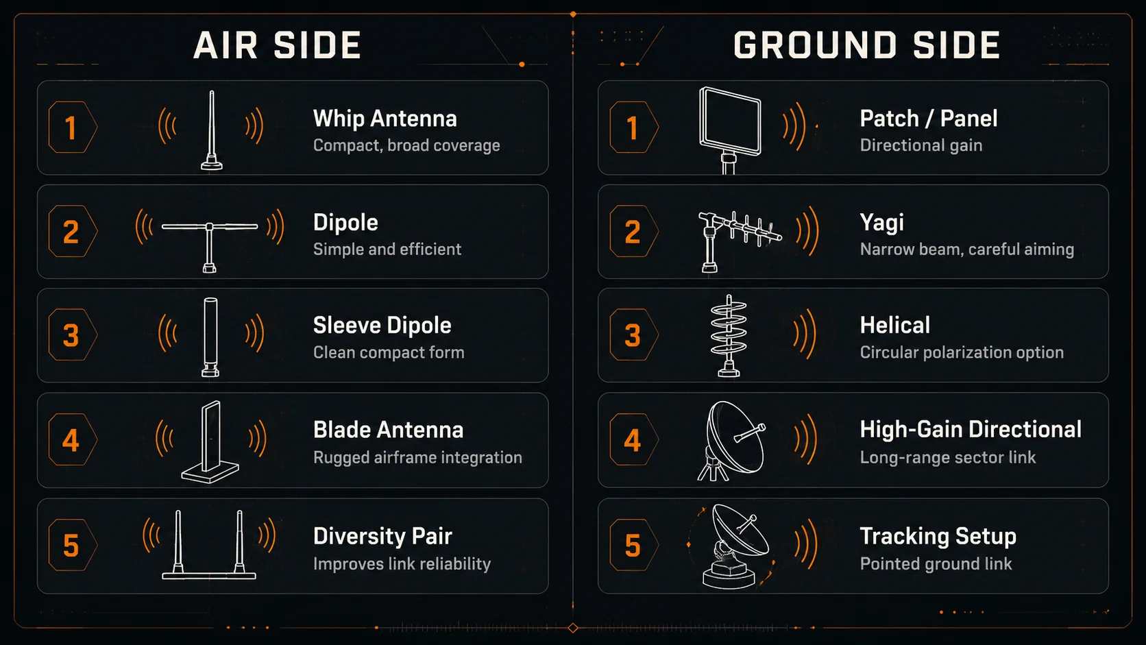
Different antenna types serve different roles. Choosing an antenna only by gain is a common mistake. The right choice depends on where the antenna is mounted, how the aircraft moves, what frequency band is used, and whether the antenna is on the air side or ground side.
2.1 Omnidirectional Antennas
Omnidirectional antennas radiate energy broadly around the antenna axis. They are widely used on UAV air units because the aircraft can move in any direction relative to the ground station.
Common examples include whip antennas, dipoles, sleeve dipoles, and compact blade-style antennas.
Their main advantage is coverage. They do not require the UAV to point toward the ground station. This makes them useful for command, telemetry, video, and IP data links where the aircraft attitude changes continuously.
The limitation is that omnidirectional does not mean equal coverage in every direction. Most omnidirectional antennas still have nulls, especially above and below the antenna axis. Placement and orientation still matter.
2.2 Dipole and Sleeve Dipole Antennas
Dipole antennas are simple, efficient, and common in UAV radio systems. A basic dipole has two radiating elements and is usually linearly polarized.
Sleeve dipoles are often used when a compact and mechanically cleaner form is required. They can provide good performance when mounted away from conductive or RF-absorbing structures.
For UAV air units, dipole-style antennas are often a practical baseline because they are lightweight, easy to mount, and provide broad coverage when placed correctly.
Their performance can degrade when they are placed too close to carbon fiber, metal plates, batteries, power wiring, or other antennas.
2.3 Whip Antennas
Whip antennas are common in compact radio systems. They are mechanically simple and easy to attach to an enclosure through an SMA, RP-SMA, MMCX, or similar RF connector.
They work well when the mounting point provides a suitable RF environment. However, in small UAVs, the available mounting surface is often limited. If the whip is close to the frame, battery, landing gear, or payload, the pattern may become distorted.
A whip antenna should not be treated as a plug-and-play range solution. Its final performance depends heavily on where it is mounted and what surrounds it.
2.4 Blade Antennas
Blade antennas are compact, rugged, and visually cleaner than exposed wire or whip antennas. They are often used when the UAV system needs a more productized and field-ready mechanical design.
A blade antenna can be easier to integrate into an airframe or enclosure. It can also be more resistant to handling damage compared to a long external whip.
The trade-off is that blade antennas still need good RF placement. If they are mounted directly against carbon fiber, metal, batteries, or dense electronics, the radiation pattern can be affected. Mechanical neatness should not come at the cost of RF visibility.
2.5 Patch and Panel Antennas
Patch and panel antennas are directional antennas. They focus energy in a specific direction instead of radiating broadly in all directions.
They are useful on the ground side because the ground station can often be pointed toward the UAV. A directional antenna can improve link margin when the aircraft is operating in a known sector.
On the air side, patch antennas are less common for general command and telemetry because the UAV attitude changes continuously. A patch antenna on the aircraft may create strong coverage in one direction but weak coverage elsewhere.
Patch and panel antennas are good tools when the mission geometry is controlled. They are poor choices when the aircraft orientation is unpredictable.
2.6 Yagi Antennas
Yagi antennas provide directional gain and are usually used on the ground side. They can be useful for long-range point-to-point links where the ground operator or tracking system can maintain direction toward the aircraft.
Their narrow beam can improve range, but it also requires pointing discipline. If the antenna is not aimed correctly, the link can degrade quickly.
For moving UAV operations, a Yagi is usually better suited to a tracking ground station than a handheld setup.
2.7 Helical Antennas
Helical antennas are often used when circular polarization is useful. They are directional and can be effective for certain video or telemetry links, especially when the aircraft orientation changes and circular polarization helps reduce polarization mismatch.
Their size and directionality usually make them more suitable for ground stations than small air units.
A helical antenna can be useful when the link is designed around a known operating band, known polarization strategy, and controlled pointing direction.
2.8 MIMO and Diversity Antenna Setups
MIMO and diversity are not single antenna types. They are antenna system arrangements.
A diversity setup uses two or more antennas so the radio system can handle signal fades, blockage, multipath, and polarization changes better than a single antenna.
For example, two air-side antennas may be placed at different locations or orientations so that one antenna remains useful when the other is blocked or poorly aligned.
The key rule is that diversity antennas must not be placed as duplicates of each other. If both antennas are mounted close together, in the same orientation, and behind the same obstruction, they may fail together.
Diversity works best when the antennas see the world differently.
3. Air-Side Antennas and Ground-Side Antennas Have Different Jobs
A UAV radio link has two ends, and the antenna strategy should not be the same on both sides.
The air-side antenna must survive movement, vibration, limited space, payload changes, and fast attitude changes. The ground-side antenna has more freedom: it can be larger, higher, directional, and mechanically supported.
3.1 Air-Side Priorities
On the UAV, the antenna should usually prioritize:
- wide coverage
- low weight
- secure mounting
- low drag
- vibration resistance
- stable performance during roll, pitch, and yaw
- clearance from batteries, carbon fiber, motors, ESCs, and payloads
The aircraft is not a fixed tower. It moves continuously. This makes predictable coverage more useful than peak gain in only one direction.
For many UAV air units, a well-placed omnidirectional or diversity antenna setup is more practical than a high-gain directional antenna.
3.2 Ground-Side Priorities
On the ground side, the constraints are different. The antenna can be placed higher, separated from noisy electronics, and pointed toward the UAV.
Ground-side systems can use:
- directional antennas
- higher-gain antennas
- antenna masts
- tracking mounts
- better diversity spacing
- lower-loss cable runs if designed carefully
This leads to a practical rule:
The air unit usually needs coverage. The ground unit can afford gain.
4. Antenna Gain Is Not Free Range
Antenna gain is often misunderstood. Higher gain does not create energy. It reshapes where the energy goes.
A higher-gain antenna usually concentrates the radiation pattern into a narrower region. This can improve performance when the UAV remains inside that region. It can also create weaker zones outside that region.
For a ground-side directional antenna, this can be useful. The antenna can focus energy toward the aircraft.
For an air-side antenna, too much gain can be risky. The UAV may bank, yaw, climb, or turn in a way that moves the ground station into a weaker part of the radiation pattern.
This is why the highest-gain antenna is not always the best UAV antenna.
Antenna gain should match the mission geometry:
- short-range inspection may benefit from broad coverage
- long-range corridor flight may benefit from ground-side directionality
- loitering missions may need stable coverage during circular movement
- low-altitude operations may be sensitive to ground reflection and blockage
- aircraft with aggressive banking may need diversity or circular polarization
In UAV communication, stable link behavior is often more important than a high peak number on the antenna datasheet.
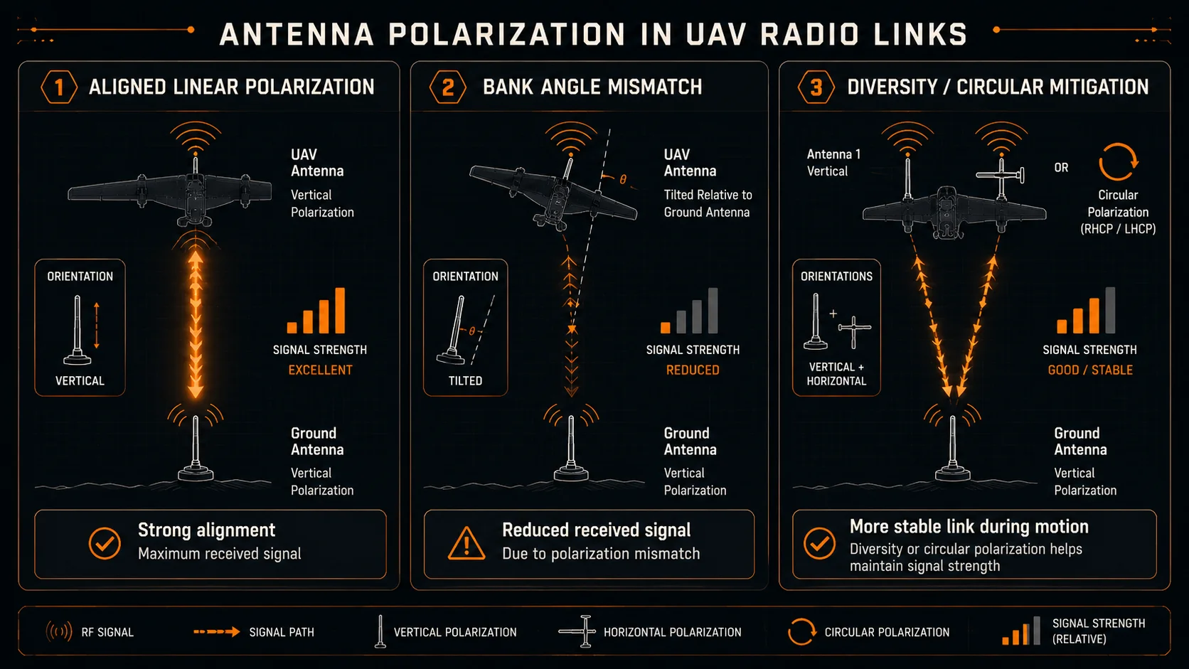
5. Polarization Matters During Flight
Antenna polarization describes the orientation of the electric field radiated by the antenna. In simple terms, two antennas communicate best when their polarization is aligned.
Common polarization types include:
- vertical polarization
- horizontal polarization
- circular polarization
If one antenna is vertically polarized and the other is horizontally polarized, the received signal can drop significantly. On a fixed installation, this is easy to control. On a UAV, it is harder because the aircraft attitude changes during flight.
When the UAV banks, pitches, or yaws, the antenna orientation changes relative to the ground antenna. This can create temporary link degradation, especially with linearly polarized antennas.
5.1 Linear Polarization
Linear polarization is common and simple. Many dipoles, whips, and blade antennas are linearly polarized.
It works well when both ends remain aligned. But UAV motion can disturb this alignment. A vertically mounted antenna on the aircraft may not remain effectively vertical during a steep bank.
5.2 Circular Polarization
Circular polarization can help when the relative orientation between antennas changes. It is often used in video links and some specialized UAV communication systems.
However, circular polarization is not automatically better in every case. The antenna type, matching polarization sense, ground-side design, and mission geometry all matter.
5.3 Diversity as a Practical Solution
Diversity is often the most practical way to handle real UAV motion. With two antennas placed in different orientations or locations, the system has a better chance of maintaining a usable signal when one antenna enters a weak condition.
Good diversity design may involve:
- physical separation
- different antenna orientations
- placement on different parts of the airframe
- avoiding shared blockage
- avoiding identical cable paths near the same noise source
Diversity is not just adding a second antenna. It is designing two antennas so they fail differently.
6. Placement Decides Real-World Antenna Performance
Antenna placement is often more important than the antenna model itself.
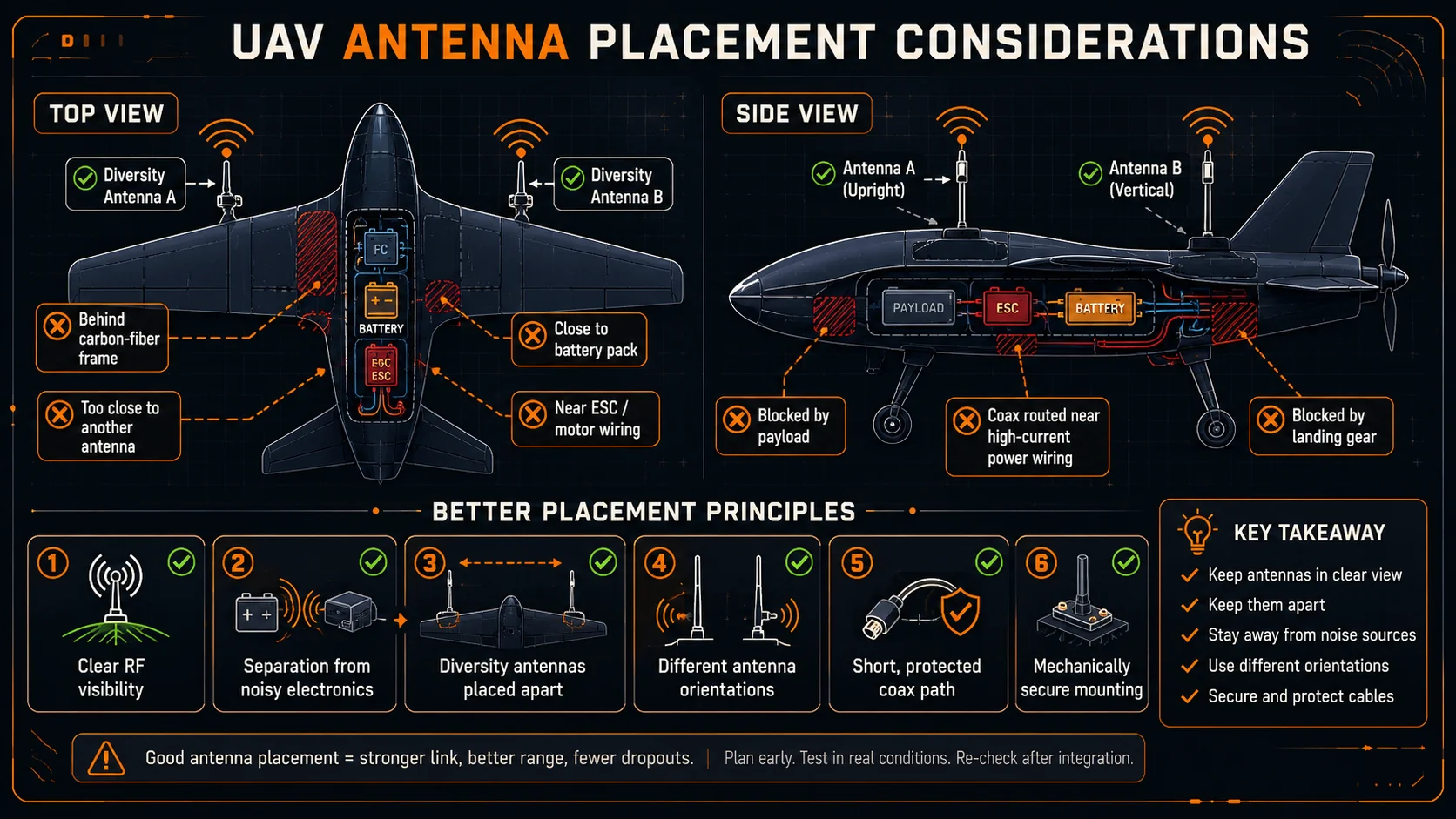
The antenna does not radiate in isolation. It interacts with the frame, battery, payload, wiring, enclosure, landing gear, and nearby antennas.
A good antenna in a poor location can create:
- distorted radiation pattern
- reduced range
- unstable RSSI
- attitude-dependent dropouts
- poor video quality
- telemetry loss
- control-link instability
- intermittent failures during turns
6.1 Avoid Carbon Fiber Shadowing
Carbon fiber is common in UAV frames, but it can strongly affect RF behavior. An antenna placed inside or directly behind carbon-fiber structure may be partially shielded.
This can create direction-dependent performance. The link may look fine in one aircraft orientation and weak in another.
Antenna placement should keep the radiating element clear of carbon-fiber plates, arms, enclosures, and payload mounts wherever possible.
6.2 Keep Antennas Away From Batteries
Battery packs are physically large and dense. They can block, detune, or distort antenna performance depending on placement and frequency.
An antenna mounted close to the battery may perform differently when the battery position, battery size, or payload configuration changes.
For repeatable performance, antennas should not be hidden behind the battery from the ground station’s expected direction.
6.3 Avoid ESCs, Motors, and High-Current Wiring
ESCs, motors, and power wiring create electrical noise and strong current transitions. Routing antenna cables or placing antennas near these components can degrade link quality.
The issue may not appear during a simple bench test. It may appear only when motors are armed, throttle changes, or the aircraft is under load.
Antenna validation should always include motor-on testing.
6.4 Keep Antennas Clear of Payloads and Landing Gear
Payloads often change between missions. Cameras, gimbals, sensors, cargo mounts, and landing gear can all obstruct antenna visibility.
Antenna placement should be checked with the real payload installed, not only with an empty aircraft.
For UAVs with underslung payloads, downward antenna visibility can be affected. For aircraft with top-mounted batteries or payloads, upward and side coverage may be affected.
6.5 Maintain Separation Between Multiple Antennas
Modern UAVs may carry several antennas:
- command and control
- telemetry
- video
- GNSS
- payload data
- companion computer Wi-Fi
- LTE or 5G modem
- remote ID or tracking module
Placing antennas too close together can create coupling, desensitization, pattern distortion, or interference problems.
Antenna separation should be planned early in the airframe design instead of being solved at the end of integration.
6.6 Place Diversity Antennas Intentionally
Diversity antennas should not be placed side by side only because it is mechanically convenient.
Useful diversity needs separation and difference. The antennas should not be blocked by the same structure at the same time. They should not have identical orientation if polarization changes are expected.
For example, one antenna may be placed vertically and another at a different orientation, depending on the radio design and operating band. The exact placement depends on the aircraft geometry, but the principle remains the same: diversity antennas should provide independent signal opportunities.
7. Cable and Connector Effects Should Not Be Ignored
Although this article is focused on antennas, the antenna does not connect to the radio magically. The RF path usually includes connectors and coax cable.
Every cable and connector adds loss. Thin coax cables are convenient for small UAVs, but they can have significant loss, especially at higher frequencies. Long coax runs may solve a mechanical placement problem while creating an RF performance problem.
Important integration points include:
- keep coax cable length as short as practical
- avoid sharp bends
- use proper strain relief
- avoid loose RF connectors
- avoid repeated twisting during assembly
- protect external connectors from moisture and dust
- avoid routing coax next to high-current motor wiring
- verify connector type and polarity before installation
Moving the antenna away from the radio can improve placement, but every extra cable length adds loss and mechanical risk.
The best antenna position is not always the closest position. The best design balances RF visibility, cable loss, mechanical protection, and serviceability.
8. Antenna Testing Should Happen Before Flight
Antenna placement should be tested before the UAV is sent to real range.
A static desk test does not represent flight. The aircraft should be tested in the configuration in which it will actually fly.
Useful pre-flight antenna tests include:
- rotate the UAV on the ground and monitor RSSI or link quality
- test with motors disarmed and armed
- test with motors running at different throttle levels
- test with the real payload installed
- test with the battery installed in its final position
- compare link behavior from the front, rear, left, right, top, and bottom
- check performance during yaw, pitch, and roll angles
- test video, telemetry, and control traffic together
- compare low-altitude and mission-altitude performance
- inspect connectors after vibration or transport
If a link becomes unstable only at a particular aircraft angle, the cause is often antenna placement, polarization, or airframe blockage.
Bench range is not flight range. Antenna placement should be validated in the aircraft’s real operating condition.
9. Common Antenna Integration Mistakes
Most antenna mistakes look small during assembly but become serious during flight.
Common mistakes include:
- selecting the highest-gain antenna without checking its pattern
- placing an antenna inside a carbon-fiber enclosure
- mounting the antenna directly behind the battery
- putting both diversity antennas in the same location
- routing coax beside ESC power wires
- using long thin coax cables without accounting for loss
- ignoring connector looseness after vibration
- testing the link without motors running
- testing without the final payload installed
- assuming RSSI on the bench represents airborne performance
- using a directional ground antenna without proper aiming
- mixing antenna polarization without understanding the link impact
These problems are avoidable when antenna planning is treated as part of the UAV design process.
10. Conclusion: Antenna Selection Is Only the Starting Point
UAV radio performance is not decided only by the radio chipset or transmit power. The antenna system plays a major role in real-world link reliability.
The right antenna type must be selected for the mission. The gain must match the flight geometry. Polarization must be considered because the aircraft is always moving. Diversity must be placed intentionally. Cable and connector losses must be controlled. Final testing must happen with the actual airframe, battery, payload, and motor conditions.
In short, antenna selection is only the starting point. Antenna placement, orientation, surrounding structure, cable routing, and flight-condition testing decide whether the radio link remains stable in real missions. For teams evaluating full-stack communication architecture, CY-2 can be assessed alongside these same antenna-engineering principles.