Blogs
The Hidden Problem in Drone Communication: Too Many Links, Not Enough Integration
Published
Learn why fragmented UAV and UGV communication stacks become fragile in the field, and how integrated radio-link architecture improves priority, latency, and debugging.
Article
Overview.
Most drone communication problems are not caused by one weak radio. They are caused by a fragmented communication stack where video, telemetry, payload access, configuration, and diagnostics all travel over separate links that were never designed to behave as one system.
A UAV radio link is rarely just a telemetry pipe anymore. Modern platforms often carry video, payload control, serial traffic, onboard computer access, and service data at the same time, so the communication problem is architectural as much as it is RF.
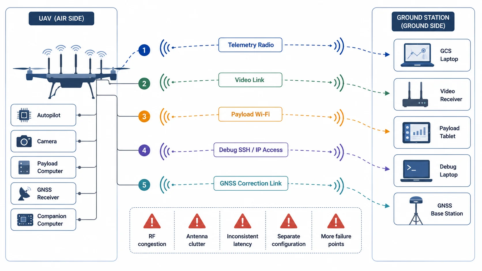
A UAV may have one link for telemetry, another link for video, another Wi-Fi connection for payload configuration, a separate serial modem for a subsystem, and sometimes a completely different network path for debugging or onboard computer access.
On paper, this looks modular.
In the field, it often becomes fragile.
Each link has its own antenna, frequency behavior, latency profile, packet loss pattern, power requirement, connector, configuration method, and failure mode. When the system works in the lab but becomes unstable outdoors, the reason is often not just RF range. The deeper issue is lack of integration between the communication paths.
Modern UAVs and UGVs need more than a radio. They need a communication architecture.
1. The typical drone communication stack
A practical unmanned system rarely sends only one type of data.
A field drone or ground robot may need to carry:
- command and control data
- autopilot telemetry
- payload telemetry
- live video
- camera control
- onboard computer access
- GNSS correction data
- health monitoring
- mission upload/download
- logs and diagnostics
- remote configuration traffic
Each of these traffic types behaves differently.
Telemetry is usually low bandwidth but sensitive to delay and continuity. Video is high bandwidth and tolerant to small packet loss, but sensitive to jitter. Command traffic is low bandwidth, but it must be prioritized. File transfer and logging traffic can consume bandwidth aggressively if not controlled. Debug access may be convenient during development but dangerous if it competes with control traffic during operation.
The problem begins when every function is assigned a separate link without a system-level communication plan.

This kind of integration pattern can feel convenient during development, but it raises antenna count, configuration burden, RF self-interference, and field failure points.
2. Why separate links become a system problem
Separate links are not always wrong. In some systems, separation is intentional and useful. For example, safety-critical control may be isolated from high-bandwidth payload data. A backup telemetry path may be intentionally independent. A test setup may use Wi-Fi for convenience while the main radio carries mission data.
The problem appears when separation happens accidentally rather than architecturally.
This usually creates five technical issues.
3. Issue one: No shared priority model
A drone communication system should not treat all packets equally.
A heartbeat message from the autopilot is not the same as a video frame. A command acknowledgement is not the same as a log upload. A camera configuration packet is not the same as a bulk file transfer.
When different traffic streams are carried by different radios, each radio makes its own independent decision. There is no common scheduler. There is no shared queue. There is no system-level understanding of which packet matters most at a given moment.
This causes strange field behavior.
The video link may look fine, while telemetry becomes unstable. The payload link may work during setup, but fail when the drone turns. A debug session may work on the ground, but become unusable after takeoff. The operator sees multiple symptoms, but the root cause is that the communication stack has no unified traffic policy.
A better architecture defines traffic priority explicitly.
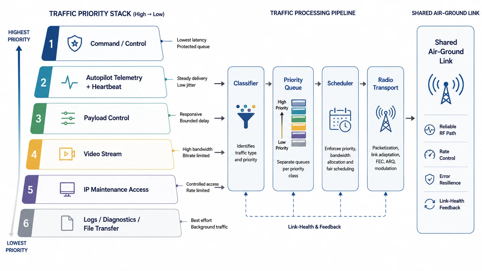
A practical priority order often looks like this:
| Priority | Traffic type | Behavior needed |
|---|---|---|
| 1 | Safety-critical command/control | Lowest latency, highest reliability |
| 2 | Autopilot telemetry and heartbeat | Consistent delivery, low jitter |
| 3 | Payload control | Low latency, moderate bandwidth |
| 4 | Video transport | High bandwidth, jitter-managed |
| 5 | Diagnostics and logs | Best effort, rate limited |
| 6 | File transfer and updates | Background only |
This does not mean all traffic must always use one physical stream. It means the system must understand traffic classes and their operational importance.
4. Issue two: Antenna count and placement become unmanageable
Every radio link needs an antenna strategy.
On small UAVs, antenna placement is not just a mechanical problem. It affects radiation pattern, polarization, cable loss, ground-plane behavior, isolation, and shadowing from the frame, battery, payload, or landing gear.
When the platform carries too many independent links, antenna placement becomes chaotic.
Common field issues include:
- antennas placed too close to carbon fiber or metal structures
- poor separation between transmitters and receivers
- coaxial cable losses caused by long internal routing
- different antennas pointing in different null directions
- polarization mismatch between air and ground
- video antenna interfering with telemetry antenna placement
- onboard electronics radiating near RF paths
- ground station antenna alignment optimized for one link but not another
Antenna clutter also increases integration time. Every added radio creates another mounting, power, EMI, cable, and enclosure problem.
A unified communication system reduces this burden by treating RF design as a platform-level concern instead of a collection of separate accessories.
5. Issue three: Latency becomes hard to predict
Drone communication is not only about bandwidth. It is also about latency and jitter.
Latency is the delay from source to destination. Jitter is the variation in that delay.
A video stream may tolerate 100 to 200 ms of latency depending on the use case, but it may break visually if jitter is uncontrolled. Telemetry may use very little bandwidth, but if messages arrive in bursts instead of a steady rhythm, the ground control station may show link warnings. Manual control traffic needs predictable response. Payload commands should not be delayed behind non-critical data.
When each subsystem has its own communication path, the total system latency becomes difficult to reason about.
For example:
Camera -> Encoder -> Packetizer -> Radio -> Receiver -> Jitter Buffer -> Decoder -> DisplayThis video path already has multiple latency sources. If telemetry and payload control are handled by different paths with different buffering and retry behavior, the operator experiences inconsistent timing across the system.
The drone may be physically operating in one moment, the video may show a slightly older moment, telemetry may be delayed differently, and payload feedback may arrive through another path entirely.
This makes diagnosis difficult.
A unified drone data link design can apply queue management, rate limiting, and transport selection more deliberately.
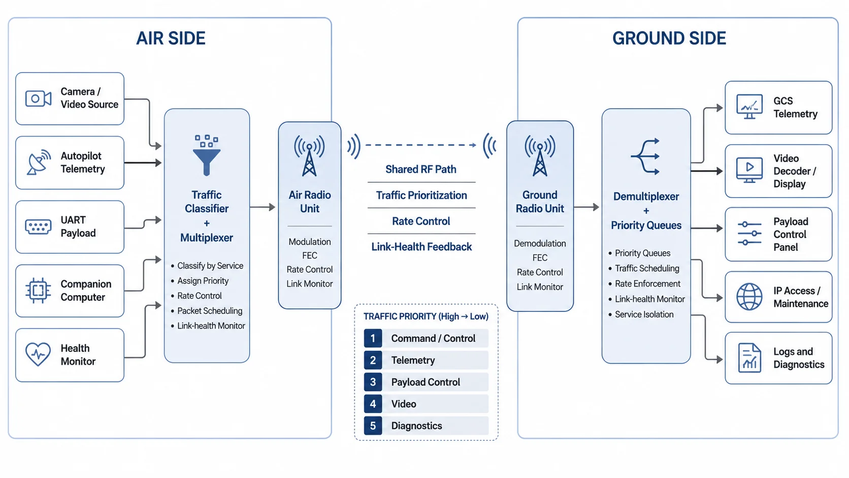
In an integrated radio-link architecture, video, telemetry, UART, payload control, and lightweight IP traffic are treated as traffic classes over a common air-ground communication foundation.
6. Issue four: Configuration gets distributed across too many devices
A drone radio link is rarely plug-and-play in a serious field system.
Someone has to configure:
- IP addresses
- serial baud rates
- telemetry endpoints
- video transport settings
- stream identifiers
- ports
- routes
- firewall rules
- ground station addresses
- camera URLs
- encoder bitrate
- radio channel or band
- transmit power
- antenna selection
- link monitoring
If every subsystem has its own configuration method, the complete setup becomes difficult to reproduce.
One device may use a web UI. Another may use a serial terminal. Another may require an app. Another may require editing a config file. Another may reset its settings after a firmware update.
This causes integration drift.
The system that worked during yesterday's bench test may fail today because one IP address changed, one baud rate was wrong, one camera stream URL changed, or one ground laptop interface was on the wrong subnet.
An integrated link should make configuration explicit.
At minimum, the system should define:
air_unit:
  role: air
  management_ip: 192.168.10.2
  radio_profile: field_test_01

services:
  telemetry:
    type: uart
    baud: 57600
    priority: high

  video:
    type: udp_stream
    source: camera0
    bitrate_limit_mbps: 4
    priority: medium

  payload_control:
    type: ip
    subnet: 192.168.20.0/24
    priority: high

  diagnostics:
    type: ip
    rate_limit_kbps: 256
    priority: low
The exact implementation may differ, but the principle matters: communication behavior should be defined as a system, not as scattered settings across unrelated devices.
7. Issue five: Debugging becomes slow and confusing
When a field link fails, the team needs to answer basic questions quickly:
- Is the radio link up?
- Is the air unit reachable?
- Is the ground unit reachable?
- Is telemetry flowing?
- Is video flowing?
- Is packet loss increasing?
- Is RSSI low?
- Is SNR low?
- Is the problem RF, routing, serial, video, or application-layer?
- Is traffic being dropped, delayed, or never generated?
In a fragmented system, each question may require a different tool.
The drone telemetry radio may show one status. The video receiver may show another. The payload Wi-Fi may have no useful diagnostics. The autopilot may report link loss even though the video is still working. The camera may stream locally but not through the air link. The operator may not know whether the failure is RF, IP routing, serial configuration, bitrate, or endpoint addressing.
An integrated system should expose link health in a way that maps to real troubleshooting.
Useful status indicators include:
| Status parameter | Why it matters |
|---|---|
| Link state | Whether the air-ground radio path is active |
| RSSI / signal level | Basic received signal strength visibility |
| SNR / noise margin | Better indicator of usable link quality |
| Packet loss | Shows degradation before complete failure |
| Retry rate | Indicates radio-layer stress |
| Queue depth | Shows congestion inside the system |
| Per-service bitrate | Identifies which stream is consuming bandwidth |
| Telemetry heartbeat age | Shows whether control data is alive |
| Video jitter buffer level | Helps diagnose unstable video |
| UART error count | Identifies serial-side integration issues |
| IP route status | Confirms network path availability |
The goal is not to expose every internal metric to the operator. The goal is to make the system diagnosable without dismantling the platform.
8. Integration does not mean mixing everything blindly
A unified radio-link architecture does not mean all data should be thrown into one uncontrolled pipe.
That would simply move the problem from hardware fragmentation to software congestion.
Good integration requires traffic engineering.
This includes:
- traffic classification
- priority queues
- bitrate limits
- packet scheduling
- congestion handling
- link-health feedback
- service isolation
- predictable addressing
- watchdogs and fail-safe behavior
- graceful degradation under weak link conditions
For example, if link quality drops, the system should not allow video to consume all available bandwidth while telemetry collapses. A better behavior is to reduce video bitrate, drop non-critical diagnostic traffic, preserve telemetry, and keep command/control responsive.
This is the difference between a radio link and a communication system.
9. Routed IP vs transparent bridging
One important design decision in UAV and UGV radio systems is whether the link should behave like a transparent Ethernet bridge or a routed IP link.
A transparent bridge tries to make devices on both sides appear as if they are on the same Layer 2 network. This can be convenient, especially during development. Devices can discover each other more easily, and existing IP workflows may continue with fewer changes.
But bridging can also carry unnecessary broadcast and multicast traffic across the air link. Protocols such as ARP, mDNS, discovery packets, and other background traffic may consume airtime. On a constrained radio path, this matters.
A routed IP design is often cleaner for field systems.
In a routed design, the air side and ground side can use defined subnets. Only required traffic is forwarded. Routes are explicit. Firewalling and service control become easier. Broadcast noise is reduced. The system becomes more predictable.
A practical UAV or UGV communication product may support lightweight IP communication without pretending that the air link is a normal office LAN. This is where an IP tunnel radio or a controlled routed-service model can be more useful than pretending the air path is a transparent Ethernet cable.
An air-ground radio link has different constraints from a wired Ethernet cable:
- lower bandwidth
- variable packet loss
- changing signal quality
- antenna orientation effects
- interference
- mobility
- power limits
- asymmetric traffic behavior
- stricter reliability expectations
So the network architecture should respect the RF environment.
10. UART still matters
In modern systems, it is tempting to think that everything should become IP-based.
But UART and serial interfaces are still common in drones, robots, payloads, GNSS devices, autopilots, and embedded modules.
UART is simple, deterministic, and widely supported. MAVLink telemetry, payload control messages, GNSS correction streams, and custom embedded protocols are often serial-first.
A serious radio-link architecture should support UART as a first-class traffic type, not as an afterthought.
Important UART considerations include:
- baud rate
- framing
- packetization
- buffering
- flow control
- serial-to-radio latency
- recovery after disconnect
- message ordering
- handling of bursty serial traffic
- mapping serial traffic into a prioritized transport class
A UART tunnel is not just "send bytes over radio." It must preserve timing well enough for the connected system to behave correctly. That is why an Ethernet and UART radio link has to be designed around service behavior, not only connector count.
11. Video is usually the dominant bandwidth consumer
Video behaves differently from telemetry and control traffic.
It may consume several megabits per second even in compressed form. It may use RTP, UDP, RTSP, SRT, WebRTC-like transport, or custom packetization depending on architecture. It may require a jitter buffer. It may tolerate some loss but not uncontrolled delay. It may need adaptive bitrate or at least defined bitrate limits.
The danger is that video can silently dominate the link.
If video is allowed to transmit without control, it can increase queue delay for other services. Even if telemetry packets are small, they may get stuck behind video bursts.
A practical multi-service radio link should treat video as a managed service.
Video handling should define:
- target bitrate
- maximum bitrate
- resolution
- frame rate
- codec
- transport protocol
- packet size behavior
- jitter buffer size
- recovery behavior
- priority relative to telemetry
- behavior under poor link conditions
In field systems, "video works" is not enough. The question is: does video work while telemetry, command, payload control, and diagnostics also remain usable?
Different data streams should not compete equally over a constrained air-ground radio link. Command/control and telemetry need predictable access, while video should be bitrate-managed and diagnostics should remain best effort.
12. What an integrated drone communication architecture looks like
A better communication architecture starts by treating the radio link as a shared system resource.
Instead of thinking:
Which radio do we use for this device?the system designer should ask:
What traffic types does the platform generate, and how should each behave over the air link?A strong architecture defines the following layers.
12.1 Physical and RF layer
This includes:
- frequency band
- transmit power
- antenna type
- antenna placement
- polarization
- cable routing
- air/ground role separation
- link budget
- interference behavior
- field test procedure
This layer determines whether the link can physically exist.
12.2 Radio transport layer
This layer handles how bytes or packets move across the RF path.
It may include:
- packetization
- retransmission strategy
- forward error handling
- rate control
- link monitoring
- channel behavior
- raw transport mode
- bidirectional data handling
This layer determines how the radio behaves under real RF conditions.
12.3 Service multiplexing layer
This is where multiple services share the link.
It should understand:
- telemetry traffic
- video traffic
- UART traffic
- IP traffic
- diagnostics traffic
- control traffic
This layer determines whether the platform behaves well when multiple subsystems are active at the same time.
12.4 Network and interface layer
This layer exposes usable interfaces to the system integrator.
It may provide:
- Ethernet access
- UART access
- USB-connected data paths
- static IP routing
- service endpoints
- payload access
- ground station connectivity
This layer determines how easily the radio can be integrated into real UAV and UGV systems.
12.5 Observability and configuration layer
This layer determines whether the system can be configured, monitored, and debugged.
It may include:
- link status
- traffic statistics
- service state
- UART status
- IP route state
- video bitrate visibility
- logs
- simple configuration profiles
- air/ground role configuration
This layer determines whether the system can be fielded repeatedly, not just demonstrated once.
13. Graceful degradation is the real test
A good communication system is not defined only by how it behaves under ideal conditions.
It is defined by how it behaves when the link becomes weak.
In real field use, link quality changes constantly because of:
- distance
- altitude
- antenna orientation
- ground reflections
- terrain masking
- platform movement
- interference
- polarization changes
- vibration
- cable or connector issues
- power supply noise
When conditions degrade, a fragmented system usually fails unevenly. One link drops, another stays up, another becomes delayed, and another gives no meaningful status.
An integrated system can degrade more intelligently.
For example:
| Link condition | Preferred system behavior |
|---|---|
| Strong link | Full video bitrate, telemetry, payload control, diagnostics |
| Moderate degradation | Reduce video bitrate, preserve telemetry and control |
| High packet loss | Drop diagnostics, reduce video, maintain heartbeat |
| Severe degradation | Preserve minimum command/telemetry path |
| Link recovery | Restore services gradually, avoid traffic burst |
This kind of behavior requires intentional architecture. It does not happen automatically just because a radio has enough peak bandwidth.
14. Why this matters for UAVs and UGVs
UAVs and UGVs are becoming more software-defined.
The onboard stack now often includes:
- autopilot
- companion computer
- camera
- encoder
- payload controller
- sensor processor
- networked devices
- logging system
- remote configuration interface
- AI/ML inference module
- mission software
As the platform becomes more capable, communication becomes more important.
The radio link is no longer just a telemetry pipe. It becomes the operational bridge between the remote platform and the human operator control system.
For UAVs, this bridge may carry video, telemetry, commands, and payload state.
For UGVs, it may carry camera streams, navigation data, control messages, sensor feedback, and remote diagnostics.
For hybrid systems, the same communication design problem appears across air, ground, and field-deployed nodes.
The common requirement is not simply "more range" or "more Mbps."
The requirement is integrated, predictable, field-usable communication.
That is true whether the platform is being framed as a UGV radio link, a UAV radio link, or a mixed-service field communications stack.
15. Practical design checklist
When designing or selecting a radio link for a UAV or UGV, ask these questions:
- What traffic types must share the link?
- Which traffic is safety-critical?
- Which traffic is latency-sensitive?
- Which traffic is bandwidth-heavy?
- Which traffic can be best effort?
- Is video rate-limited?
- Is telemetry protected from congestion?
- Are UART and IP handled as first-class services?
- Is the system routed, bridged, or both?
- Are IP addresses and ports clearly defined?
- Can the operator see link health?
- Can the engineer debug per-service failures?
- What happens when the link becomes weak?
- What happens when the link recovers?
- Can the same configuration be reproduced across field tests?
If these questions are not answered, the system may work during demos but become difficult to trust during real deployment.
16. Conclusion
The hidden problem in drone communication is not always range.
It is fragmentation.
Too many independent links create too many antennas, too many configurations, too many latency behaviors, and too many failure modes. The platform may appear modular, but the communication system becomes harder to predict and harder to debug.
Modern UAVs and UGVs need integrated radio-link architecture.
That means treating video, telemetry, UART, IP access, payload control, and diagnostics as parts of one communication design. Each traffic type should have a defined role, priority, bandwidth behavior, and failure response.
A good radio link is not only about moving data over distance.
It is about moving the right data, at the right priority, with predictable behavior, under changing field conditions.
That is where drone communication becomes system engineering.