Blogs
What Is a UAV Radio Link? Video, Telemetry, UART, and IP Data Explained
Learn how UAV radio links carry video, telemetry, UART, and IP data between drones and ground stations, and what specs matter when selecting a drone data link.
Article
Overview.
A UAV is not only a flying camera. Even a small drone can have multiple systems exchanging data at the same time: the autopilot sends telemetry, the camera sends video, the payload may need serial control, and the onboard computer may expose IP services such as dashboards, APIs, or configuration pages.
A UAV is not only a flying camera. Even a small drone can have multiple systems exchanging data at the same time: the autopilot sends telemetry, the camera sends video, the payload may need serial control, and the onboard computer may expose IP services such as dashboards, APIs, or configuration pages.
For a new drone company, this can quickly become confusing. Should video use one radio and telemetry use another? Should the onboard computer have a separate Wi-Fi link? What happens if the payload needs UART? Can one link carry everything?
This article explains what a UAV radio link is, what types of data it carries, what numbers matter, and how to choose a practical communication architecture for UAV and UGV platforms.
1. What is a UAV radio link?
A UAV radio link is the wireless communication path between the drone and the ground side.
In a basic setup, the radio link connects:
| Air side | Ground side |
|---|---|
| Drone / UAV / UGV | Operator laptop or ground control station |
| Autopilot | GCS software |
| Camera | Video monitor or video processing system |
| Onboard computer | Ground-side network |
| Payload controller | Operator interface |
| Sensors | Logging or monitoring system |
The radio link may carry only one type of data, such as telemetry, or it may carry multiple types of traffic over a single wireless connection.
A modern UAV radio link can carry:
- Live video
- Autopilot telemetry
- Command and control data
- UART/serial payload data
- IP packets
- Web dashboard access
- SSH or configuration access
- Payload health monitoring
- Mission upload/download data
For small and medium UAVs, the biggest design question is whether to use separate links for each function or one integrated data link that carries multiple traffic types together.
2. Why drone communication is more than just video
Many new drone teams first think about video range. This is natural because live video is the most visible part of a drone system.
But in real UAV operation, video is only one part of the communication requirement.
A typical drone may need:
| Data type | Example | Typical bandwidth |
|---|---|---|
| Autopilot telemetry | MAVLink, GPS, attitude, battery, mode, RC status | 10 kbps – 300 kbps |
| Command and control | Mode change, mission command, velocity command, payload trigger | 5 kbps – 100 kbps |
| Low-rate payload data | Sensor readings, small status packets, UART messages | 1 kbps – 500 kbps |
| HD video | 720p / 1080p compressed H.264/H.265 stream | 2 Mbps – 12 Mbps |
| High-quality video | 1080p high bitrate / low compression | 8 Mbps – 25 Mbps |
| IP access | Web UI, SSH, API, diagnostics, logs | Bursty, usually <1 Mbps average |
| File/log transfer | Downloading logs, images, mission data | Depends on file size and link margin |
A telemetry-only radio may be enough for basic flight control, but it cannot carry useful video. A video transmitter may show camera output but may not give proper access to the autopilot or onboard computer. A normal Wi-Fi link may work during testing but may become unreliable when the aircraft is moving, the antenna orientation changes, or the range increases.
This is why UAV radio design must consider the full data requirement, not just one headline number.
3. Main types of data carried by a UAV radio link
3.1 Video stream
Video is usually the highest-bandwidth traffic in a UAV link.
For practical UAV operation, video is normally compressed before transmission. The most common formats are H.264 and H.265. The stream may be carried over RTSP, RTP, UDP, TCP, SRT, WebRTC, or a custom transport depending on the system design.
Typical video bitrate numbers:
| Video mode | Practical bitrate range |
|---|---|
| 480p low-latency monitoring | 0.8 – 2 Mbps |
| 720p 30 FPS | 2 – 5 Mbps |
| 1080p 30 FPS | 4 – 12 Mbps |
| 1080p 60 FPS | 8 – 20 Mbps |
| 4K compressed monitoring | 15 – 40 Mbps |
For most UAV and UGV applications, a stable 720p or 1080p stream is more useful than chasing maximum resolution. Link stability, latency, and graceful degradation are usually more important than peak bitrate.
3.2 Telemetry
Telemetry is the operational health and navigation data from the UAV.
It may include:
- GPS position
- Altitude
- Roll, pitch, yaw
- Battery voltage and current
- Flight mode
- Armed/disarmed state
- EKF or navigation status
- RC link status
- Mission progress
- Error messages
For ArduPilot and PX4-based systems, telemetry is often carried using MAVLink over UART, UDP, or TCP.
Telemetry bandwidth is usually small compared to video. A normal MAVLink stream may use only tens or hundreds of kilobits per second. However, telemetry must be reliable because it directly affects operator awareness and safety.
Typical telemetry rates:
| Telemetry use case | Typical bandwidth |
|---|---|
| Basic status telemetry | 10 – 50 kbps |
| Normal GCS telemetry | 50 – 200 kbps |
| High-rate logs / debug streams | 200 kbps – 1 Mbps |
| Multiple vehicles or payload telemetry | 200 kbps – 2 Mbps |
3.3 UART / serial data
Many UAV payloads and autopilots still use UART.
UART may be used for:
- Autopilot telemetry
- GPS module data
- Gimbal command
- Rangefinder output
- Payload controller messages
- Companion computer serial bridge
- Custom embedded sensor data
A useful UAV radio link should allow UART traffic to be carried between air side and ground side.
Common UART baud rates:
| Baud rate | Common use |
|---|---|
| 9,600 | Low-rate sensors or legacy devices |
| 57,600 | Basic telemetry |
| 115,200 | Common MAVLink telemetry |
| 230,400 | Higher-rate telemetry |
| 460,800 | High-rate serial data |
| 921,600 | High-rate payload or debug data |
| 1,500,000+ | Possible in some systems, but cable quality and processor load matter |
For most drone systems, 57,600 to 921,600 baud is the practical working range.
3.4 IP data
IP support is one of the biggest differences between a simple telemetry radio and a modern UAV data link.
If the air side and ground side are on the same IP network, the operator can access devices on the drone just like network devices.
Examples:
| IP workflow | Example |
|---|---|
| Camera access | Open IP camera stream on ground laptop |
| Onboard computer access | SSH into companion computer |
| Web dashboard | View onboard web UI |
| API access | Send commands to payload software |
| File transfer | Download logs or images |
| Diagnostics | Ping, HTTP, MQTT, ROS bridge, custom TCP/UDP |
| Video transport | RTSP, UDP, TCP, SRT, WebRTC |
This is very useful for drone companies because development, integration, testing, and field debugging become easier.
Instead of connecting a laptop physically to the drone, the engineer can access the onboard network through the radio link.
4. Traditional multi-link setup vs integrated data link
A traditional UAV communication setup may use separate links:
| Function | Traditional approach |
|---|---|
| Video | Separate analog or digital video transmitter |
| Telemetry | Separate telemetry radio |
| Payload control | Separate serial bridge |
| Onboard computer access | Separate Wi-Fi or Ethernet access |
| Configuration | Physical cable or local Wi-Fi |
| Logging | Manual download after landing |
This approach can work, but it increases complexity.
Problems with separate links:
- More antennas on the drone
- More power consumption
- More wiring
- More RF interference
- More configuration work
- More ground-side devices
- More failure points
- More mounting and integration effort
- More difficult debugging
An integrated UAV data link carries multiple traffic types over one air-ground connection.
| Function | Integrated data link approach |
|---|---|
| Video | Sent as IP stream |
| Telemetry | Sent as UDP/TCP or serial-over-IP |
| UART | Bridged or packetized over the link |
| Payload data | Sent over IP or serial tunnel |
| Onboard access | Available through IP tunnel |
| Monitoring | Ground-side network access |
This is often better for UAV/UGV companies building repeatable products because the communication architecture becomes easier to standardize.
5. Important specifications when choosing a UAV radio link
5.1 Frequency band
Common UAV communication bands include 433 MHz, 868 MHz, 915 MHz, 1.4 GHz, 2.4 GHz, and 5 GHz.
Each band has trade-offs.
| Band | Strength | Limitation |
|---|---|---|
| Sub-GHz | Better propagation, longer range at low data rate | Low bandwidth, usually not suitable for HD video |
| 2.4 GHz | Common ecosystem, moderate bandwidth | Crowded band, Wi-Fi/Bluetooth interference |
| 5 GHz | Higher bandwidth, cleaner channels in many areas | Requires better line-of-sight, more sensitive to obstruction |
| Licensed bands | Better control and reliability | Regulatory approval and licensing required |
For video + telemetry + IP traffic, 5 GHz can be practical because it offers higher bandwidth. But the antenna system and line-of-sight condition become important.
5.2 Range
Range is not a fixed number. It depends on:
- RF output power
- Receiver sensitivity
- Antenna gain
- Antenna polarization
- Antenna height
- Fresnel zone clearance
- Channel bandwidth
- RF noise
- Aircraft orientation
- Ground station antenna tracking or placement
- Weather and terrain
- Regulatory power limits
A realistic public specification should avoid claiming only a best-case number.
Better wording:
| Range class | Practical meaning |
|---|---|
| 500 m – 1 km | Easy field testing, low-height UGV, campus/industrial area |
| 1 – 3 km | Typical short UAV/UGV line-of-sight work |
| 3 – 5 km | Requires good antennas, clear LOS, proper mounting |
| 5 – 10 km | Requires careful antenna design, ground-side antenna placement, clean RF environment |
| 10 km+ | Should be treated as deployment-specific and validated by field testing |
For a 5 GHz UAV data link, 1–5 km is a realistic conservative public range for many deployments. Longer distances may be possible, but only with the correct antenna system and clean line-of-sight.
5.3 Throughput and data rate
Radio datasheets often mention PHY rate. PHY rate is not the same as usable application throughput.
For example, an 802.11ac 2×2 radio may advertise up to 867 Mbps PHY rate in ideal 80 MHz mode. But real application throughput is lower due to:
- Protocol overhead
- Channel width
- Signal quality
- Retransmissions
- Interference
- Distance
- Encryption overhead
- CPU and interface limits
- Antenna orientation
- Network traffic mix
Practical rule:
| PHY / link condition | Practical application planning |
|---|---|
| Very strong short-range link | Tens to hundreds of Mbps may be possible |
| Moderate field link | Plan for 10–50 Mbps usable throughput |
| Longer range link | Plan for 2–20 Mbps depending on margin |
| Weak edge-of-range link | Prioritize telemetry and reduce video bitrate |
A good UAV communication system should allow video bitrate control. If the link margin drops, the video bitrate should be reduced before telemetry becomes unstable.
5.4 Latency
Latency matters for piloting, gimbal control, surveillance, target tracking, and teleoperation.
Total latency includes:
- Camera exposure
- Video encoder delay
- Network packetization
- Wireless link delay
- Jitter buffer
- Decoder delay
- Display delay
Typical numbers:
| Workflow | Realistic latency range |
|---|---|
| UART telemetry only | 10 – 100 ms |
| IP telemetry | 20 – 150 ms |
| Low-latency 720p video | 80 – 200 ms |
| Normal 1080p video | 150 – 400 ms |
| Buffered RTSP/WebRTC/SRT stream | 200 ms – 1 s+ |
| Poor link with retransmissions | Highly variable |
For manual FPV flying, ultra-low latency is critical. For inspection, mapping, surveillance, robotics, and payload monitoring, stable 100–400 ms video latency is often acceptable.
5.5 Channel bandwidth
A wider channel can carry more data but may reduce range and increase interference sensitivity.
| Channel bandwidth | Typical use |
|---|---|
| 10 MHz | Better link robustness, lower throughput |
| 20 MHz | Balanced range and throughput |
| 40 MHz | Higher video throughput, needs cleaner RF |
| 80 MHz | Maximum throughput, usually best for short-range clean environments |
For UAV field use, 20 MHz or 40 MHz is often more practical than always using 80 MHz.
5.6 Antenna system
Antennas often matter more than the radio module.
Important antenna factors:
- Gain
- Polarization
- Radiation pattern
- Cable loss
- Mounting position
- Ground plane
- Diversity or MIMO spacing
- Airframe blockage
- Vibration
- Connector quality
Typical antenna choices:
| Antenna type | Use case |
|---|---|
| Small omni antenna | Compact drone, short range |
| High-gain omni | Ground vehicle or fixed ground station |
| Patch antenna | Directional ground station |
| Sector antenna | Wider directional coverage |
| Circular polarized antenna | Helps with orientation changes and multipath |
| Diversity pair | Improves link stability |
For 2×2 MIMO radios, both antenna ports should be used properly. Leaving one antenna disconnected or placing both antennas too close together can reduce performance.
5.7 Power consumption
Power matters on UAVs because every watt reduces endurance.
A compact embedded UAV data link may consume:
| Condition | Approximate power range |
|---|---|
| Idle / low traffic | 3 – 6 W |
| Normal telemetry + IP | 4 – 8 W |
| Video streaming | 6 – 12 W |
| Peak RF + processing load | 8 – 15 W |
The final number depends on radio activity, onboard processing, connected camera, USB devices, Ethernet load, and thermal design.
For small UAVs, power supply design should include margin. If the radio section can draw up to around 1.8 A at 5 V, the power system should not be designed exactly at the limit. A 5 V rail with 3 A or higher capacity is often safer depending on the complete system.
5.8 Security
A UAV data link should not be left open.
Security may include:
- WPA2/WPA3-class wireless encryption
- Strong passphrase
- IP firewalling
- Device allowlist
- VPN tunnel
- SSH key-based access
- Disabled unused services
- Separate telemetry and maintenance networks
- Encrypted application-level protocols
For development, teams often keep the network open or simple. For deployment, this should be tightened.
5.9 Interfaces
A useful UAV radio link should expose the interfaces needed by real systems.
Common interfaces:
| Interface | Use |
|---|---|
| Ethernet | IP camera, onboard computer, ground laptop, network switch |
| USB | Camera, modem, service access, configuration, peripheral integration |
| UART | Autopilot telemetry, payload serial data |
| Power input | Vehicle-side power |
| Antenna ports | External RF antennas |
| Web UI | Configuration and monitoring |
| GPIO / status LEDs | Health and link state |
Ethernet is especially important because many modern payloads and cameras are IP-based.
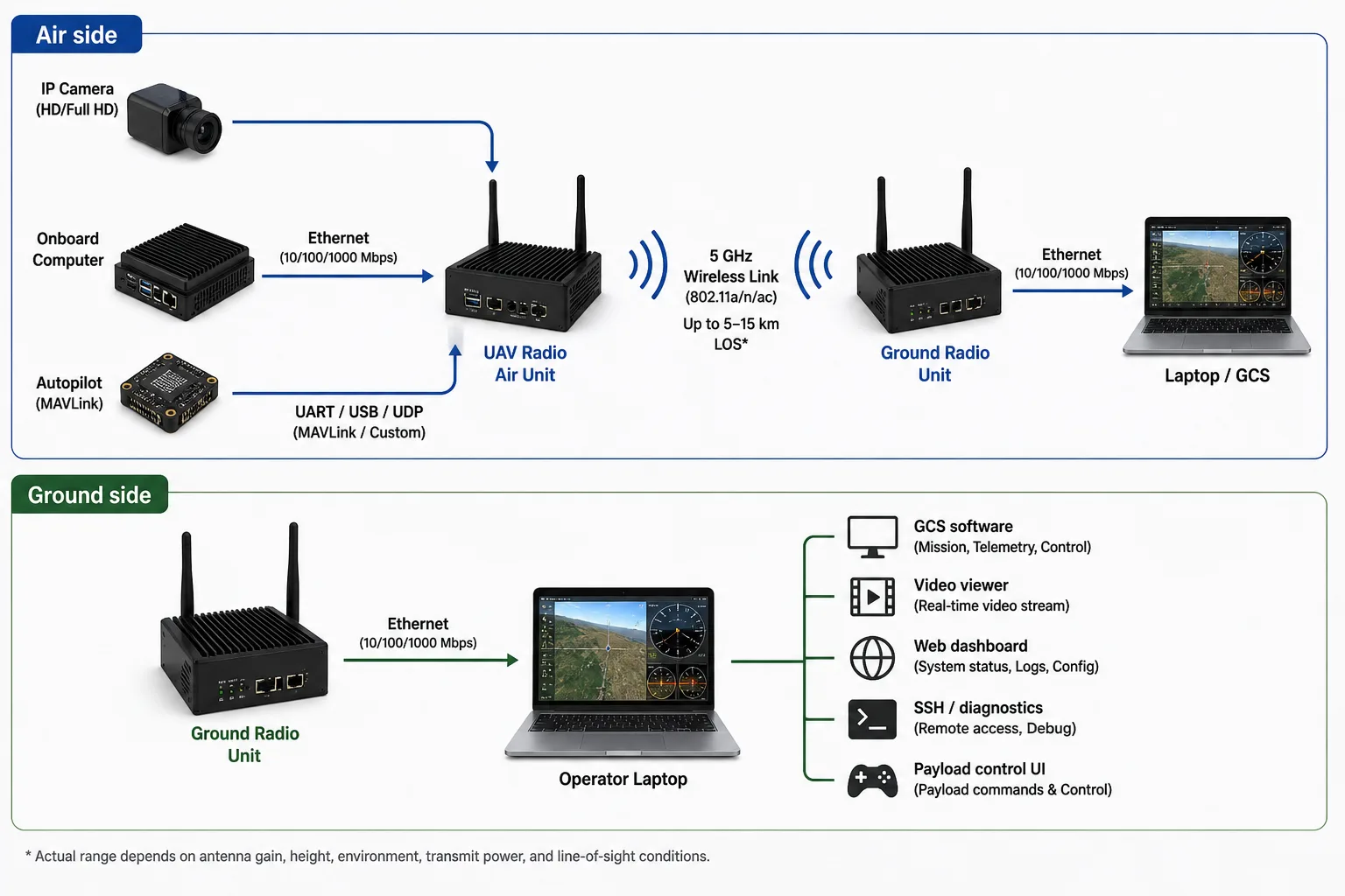
6. Example UAV communication architecture
A practical integrated UAV radio setup may look like this:
In this architecture, the radio link behaves like a network path between the drone and the operator.
The operator can receive video, monitor telemetry, access the onboard computer, and control payload software through one communication system.
7. Example bandwidth planning
Let us consider a practical UAV with one camera, one autopilot, and one onboard computer.
| Traffic | Estimated bandwidth |
|---|---|
| 1080p H.264 video stream | 6 Mbps |
| MAVLink telemetry | 100 kbps |
| Payload status | 50 kbps |
| Web dashboard | 200 kbps average |
| SSH/diagnostics | Bursty, <500 kbps average |
| Safety margin | 3–5 Mbps |
A realistic planning budget may be:
Video:        6.0 Mbps
Telemetry:    0.1 Mbps
Payload:      0.05 Mbps
Dashboard:    0.2 Mbps
Diagnostics:  0.5 Mbps
Margin:       5.0 Mbps
-----------------------
Total:       ~11.85 Mbps
This means the system should be planned for at least 12 Mbps of stable application throughput, not just 12 Mbps peak throughput.
If the link is expected to operate at longer range, it is better to reduce video bitrate to 2–4 Mbps and preserve telemetry stability.
8. How to think about video quality vs link stability
New teams often configure video at a high bitrate because it looks good during bench testing.
For example:
| Setting | Bench result | Field result |
|---|---|---|
| 1080p, 20 Mbps | Looks excellent nearby | May break at range |
| 1080p, 8 Mbps | Good quality | More stable |
| 720p, 3 Mbps | Acceptable monitoring | Much more robust |
| Adaptive bitrate | Best practical behavior | Requires software support |
For UAV operations, the best video link is not always the highest bitrate link. It is the one that remains usable as range, orientation, and RF conditions change.
A good field configuration starts conservative, validates stability, and then increases bitrate if link margin allows.
9. Point-to-point, point-to-multipoint, and mesh
Point-to-point
Point-to-point means one air unit communicates with one ground unit.
This is the simplest and most reliable architecture for most UAV and UGV systems.
Use this when:
- One vehicle is operated by one ground station
- Video and telemetry are the main traffic types
- Reliability is more important than network complexity
- The vehicle has one operator or one control station
Point-to-multipoint
Point-to-multipoint means one ground station communicates with multiple vehicles or one vehicle shares data with multiple ground clients.
This can be useful but requires careful bandwidth planning.
Example:
| Scenario | Challenge |
|---|---|
| One ground station, multiple drones | Shared bandwidth and interference |
| One drone, multiple viewers | Video distribution load |
| One fleet, one command center | Routing and addressing complexity |
Mesh
Mesh means multiple radio nodes can forward traffic for each other.
Mesh is attractive on paper, but it is not automatically better. For UAVs, mesh can introduce:
- Extra latency
- Routing complexity
- Bandwidth sharing
- Hidden-node problems
- More difficult debugging
- Link instability if nodes move quickly
- Difficult quality-of-service management
Mesh should be used only when the mission actually needs it and after proper field validation.
For many UAV companies, a strong point-to-point link is a better first product architecture than an untested mesh network.
10. Ethernet bridge and IP tunnel behavior
A transparent Ethernet bridge or IP tunnel means the ground-side laptop can communicate with air-side network devices as if they are connected over a long wireless cable.
This enables workflows such as:
Ground laptop -> open camera RTSP stream from drone
Ground laptop -> SSH into onboard computer
Ground laptop -> access payload web dashboard
Ground laptop -> receive MAVLink over UDP
Ground laptop -> send payload commands over TCP/UDP
For drone companies, this is very powerful because it simplifies integration.
Instead of building a custom protocol for everything, teams can use standard IP tools:
- ping
- SSH
- HTTP
- RTSP
- UDP
- TCP
- MQTT
- MAVLink over UDP
- custom APIs
A transparent IP link also makes debugging easier during development and field testing.
11. Practical design advice for new drone companies
Start with the data budget
Before selecting a radio, write down every data stream.
Example:
| Data stream | Direction | Required bandwidth | Latency sensitivity |
|---|---|---|---|
| Camera video | Air to ground | 3–8 Mbps | Medium to high |
| Telemetry | Bidirectional | 50–200 kbps | High |
| Payload command | Ground to air | <100 kbps | High |
| Web dashboard | Air to ground / bidirectional | 100 kbps – 1 Mbps | Medium |
| Logs | Air to ground | Bursty | Low |
Then add a safety margin.
Do not plan around peak datasheet numbers
If a radio advertises a very high PHY rate, do not assume that number is available at range. Design around practical application throughput.
For field UAV systems, it is better to design for a stable 5–20 Mbps link than to depend on a peak rate that appears only during bench testing.
Prioritize telemetry stability
If video becomes poor, the operator can still make decisions. If telemetry becomes unreliable, the operator may lose awareness of the aircraft state.
A good system should protect telemetry and command traffic even when video bandwidth is reduced.
Use proper antennas
A poor antenna placement can destroy an otherwise good radio system.
Avoid:
- Mounting antennas directly against carbon fiber
- Placing both MIMO antennas too close together
- Using long lossy RF cables
- Blocking antennas with batteries or metal frames
- Ignoring polarization
- Testing only on the bench
Test at increasing range
A practical test sequence:
| Test stage | Purpose |
|---|---|
| Bench test | Verify interfaces and configuration |
| 50 m test | Verify basic RF and video |
| 200 m test | Check antenna orientation and link quality |
| 500 m test | Validate operating bitrate |
| 1 km test | Confirm stability under motion |
| 3 km+ test | Validate real mission profile |
| Edge-of-range test | Understand failure behavior |
Do not start with maximum range. First understand how the link behaves when signal quality slowly degrades.
12. Where CY-2 fits
CY-2 is designed as a compact UAV/UGV radio link for carrying video, telemetry, UART, and IP traffic between a vehicle-side unit and a ground-side unit.
A typical CY-2 deployment can support:
- IP camera or USB camera video workflow
- Autopilot telemetry
- UART data transport
- IP tunnel-style access
- Ground-side laptop/GCS connectivity
- Onboard computer access
- Payload monitoring and control
- Local configuration and diagnostics
The intended use is not only “video transmission” or only “telemetry transmission.” The goal is to provide a practical mixed-data communication link for UAV, UGV, and robotics platforms.
For early-stage drone companies, this reduces integration complexity because the same communication system can support flight testing, payload development, video monitoring, and field debugging.
13. Frequently asked questions
Can one UAV radio link carry video and telemetry together?
Yes. A modern digital UAV data link can carry video, telemetry, and IP traffic together if it has enough throughput and the network is configured properly. Video usually consumes most of the bandwidth, while telemetry uses much less bandwidth but requires higher reliability.
What is the difference between a telemetry radio and a UAV data link?
A telemetry radio usually carries low-rate flight data, such as MAVLink messages. A UAV data link is broader. It can carry telemetry, video, IP packets, payload control, onboard computer access, and other network traffic.
Is 5 GHz suitable for UAV communication?
Yes, 5 GHz can be suitable for UAV communication when higher bandwidth is required, especially for video and IP data. However, it needs better line-of-sight and antenna planning compared to lower-frequency links.
What range can a UAV radio link achieve?
Range depends on RF power, antenna gain, channel bandwidth, line-of-sight, RF noise, and mounting. For 5 GHz UAV links, 1–5 km is a realistic conservative planning range for many field deployments. Longer ranges should be validated with the actual antenna and mission profile.
What bitrate is needed for drone video?
A practical 720p video stream may use 2–5 Mbps. A practical 1080p stream may use 4–12 Mbps. Higher bitrates improve quality but reduce link margin at range.
Can IP cameras work over a UAV radio link?
Yes. If the radio link supports IP networking, an IP camera can stream to the ground side using protocols such as RTSP, UDP, TCP, or other network transport methods.
Can a UAV radio link provide SSH or web dashboard access?
Yes, if the link provides IP tunnel or Ethernet bridge-style behavior. This allows the ground-side laptop to access the onboard computer, web dashboard, logs, or payload services.
Is mesh always better for drone networks?
No. Mesh can help in some multi-node missions, but it adds routing complexity, latency, and bandwidth sharing. For many UAV products, point-to-point communication is simpler and more reliable.
Should video and telemetry be on separate radios?
Sometimes, yes. For critical systems or very long-range systems, separate links may be preferred. But for many small and medium UAV/UGV platforms, one integrated data link is simpler and easier to deploy.
14. Conclusion
A UAV radio link should be selected based on the full communication requirement, not only range or peak data rate.
For modern UAV and UGV platforms, the link often needs to carry:
- Live video
- Autopilot telemetry
- UART payload data
- IP traffic
- Onboard computer access
- Payload monitoring and control
The most practical architecture for many drone companies is an integrated data link that carries mixed traffic over one air-ground connection. This reduces wiring, antennas, RF complexity, and integration effort.
When evaluating a UAV radio link, focus on realistic numbers: usable throughput at range, latency under load, antenna behavior, power consumption, interface support, and failure behavior. A stable 5–20 Mbps field link with reliable telemetry is often more valuable than a high peak datasheet rate that only works in ideal conditions.
For new drone companies, the best approach is to start with a clear data budget, choose the right antenna system, test progressively, and design the link so that telemetry and command traffic remain reliable even when video bandwidth is reduced.
Related
Read next.
Related page
UAV Radio Link
Explore more context on this topic and see how it connects to CY-2 deployments.
Learn moreRelated page
Drone Data Link
Explore more context on this topic and see how it connects to CY-2 deployments.
Learn moreRelated page
Drone Telemetry Radio
Explore more context on this topic and see how it connects to CY-2 deployments.
Learn moreRelated page
IP Tunnel Radio
Explore more context on this topic and see how it connects to CY-2 deployments.
Learn moreRelated page
Features
Explore more context on this topic and see how it connects to CY-2 deployments.
Learn moreRelated page
Contact
Explore more context on this topic and see how it connects to CY-2 deployments.
Learn more